1. NPAP ERD Overview
As NPAP is a highly customizable IP Core subsystem, we provide multiple designs with different parameterizations for multiple off-the-shelf FPGA boards to cover all key functions NPAP offers.
Available ERDs lists the available MLE NPAP ERDs. Depending on the off-the-shelf FPGA board we may have multiple, different ERDs as a choice for evaluation. Below the table each ERD is described in more detail including the parameterization and specific hardware platform related details, to help you choose a specific ERD and simplify your evaluation process. The default parameterization is shown in Default Parameters, if an ERD deviates from those defaults it is noted below.
Important
Please always follow the vendor documentation for the off-the-shelf FPGA board, prior to setting up and starting!
The Status column in the table indicates the current availability and development stage of each design:
Ready: The design is stable, tested, and available for customer evaluation upon request.
EOL: The design is available for internal testing and may be provided to partners for preliminary evaluation. However, the underlying hardware (i.e. FPGA board and/or FPGA device) was discontinued.
Early Access: The design is available for internal testing and may be provided to partners for preliminary evaluation.
In Development: The design is actively being worked on and is not yet available for testing.
Road Map: The design is planned for a future release, but active development has not yet started.
Please see here for the default NPAP Compile-Time parameterization:
Note
The table reflects NPAP ERD version 3.4.11.
ERD Number |
Board |
Status |
ETH Link |
Subsection |
|---|---|---|---|---|
ERD 0 |
AMD ZCU102 |
Ready |
2x 1G |
|
ERD 1 |
AMD ZCU102 |
Ready |
1x 10G |
|
ERD 2 |
MLE NPAC-KETCH |
Ready |
2x 10G |
|
ERD 3 |
AMD ZCU111 |
Ready |
1x 25G |
|
ERD 4 |
MLE NPAC-KETCH |
Road Map |
1x 40G |
|
ERD 5 |
AMD ZCU111 |
Early Access |
1x 100G |
|
ERD 7 |
Microchip MPF300 |
Early Access |
1x 10G |
|
ERD 8 |
Trenz TE0950 |
Early Access |
1x 25G |
|
ERD 10 |
AMD Alveo U200 |
EOL |
1x 25G |
|
ERD 11 |
AMD Alveo U55C |
Early Access |
4x 25G |
|
ERD 12 |
Lattice Avant-G |
Early Access |
1x 25G |
|
ERD 13 |
Arrow Agilex 5E |
Early Access |
1x 10G |
|
ERD 14 |
AMD ZCU111 |
Early Access |
2x 10G |
|
ERD 15 |
Avnet Tria AUB15P |
Ready |
1x 10G |
|
ERD 16 |
AMD Alveo V80 |
Early Access |
2x 25G |
Work in Progress |
ERD 100 |
AMD ZCU102 |
Ready |
1x 10G (Hybrid) |
|
ERD 101 |
AMD ZCU102 |
Ready |
1x 10G |
|
ERD 105 |
MS Storey Peak |
Early Access |
2x 10G |
Work in Progress |
In the following subsections the ERD config is visualized in a table with the following columns:
NPAP Instance: Which Instance the row is referring to.
Eth Link: The bandwidth of the ethernet link connected to the instance.
MAC Clock: ‘Sync’ if MAC clock is the same as the NPAP clock, ‘Async’ if the clocks differ.
Netperf: Whether a Netperf IP Core is included in the instance.
TCP User Sns: Number of TCP User Sessions of the instance.
UDP User Sns: Number of UDP User Sessions of the instance.
IPv4 Address: Default IPv4 address of the instance.
SFP Port No.: USed SFP Port, visualized in a figure in the ERD’s board section.
1.1. ERDs on AMD ZCU102
Board Overview
SoC: Zynq UltraScale+ XCZU9EG-2FFVB1156 MPSoC
Board Vendor: AMD
Product Page: AMD ZCU102 Product Page
User Guide: ZCU102 Evaluation Board User Guide (UG1182)
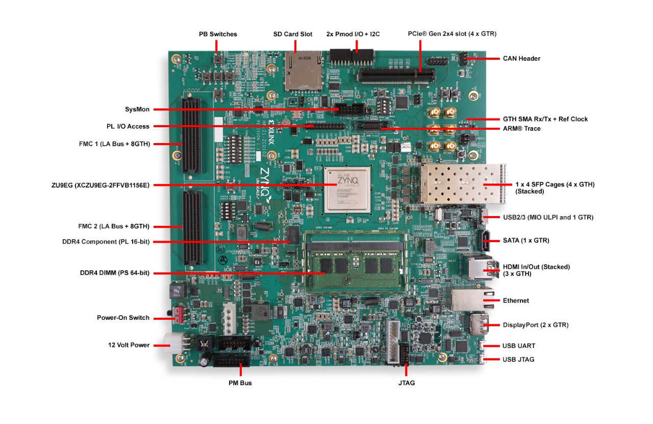
Figure 1.1 AMD ZCU102 Evaluation Kit (figure from the AMD ZCU102 Product Page)
We currently offer four ERDs for the AMD ZCU102 evaluation board: ERD 0 (2x1G), ERD 1 (1x10G), ERD 100 (1x10G) and ERD 101 (1x10G). In all ERDs except ERD 100: control via NPAP HAL is possible via the USB-UART port on the ZCU102. Figure 1.2 shows both the SFP ports and the UART port on the ZCU102, which are referenced in the ERD overview tables. In ERD 100 access to the AXI4-lite register space is provided via the processing system, for more details refer to Using Hybrid Evaluation Reference Designs.
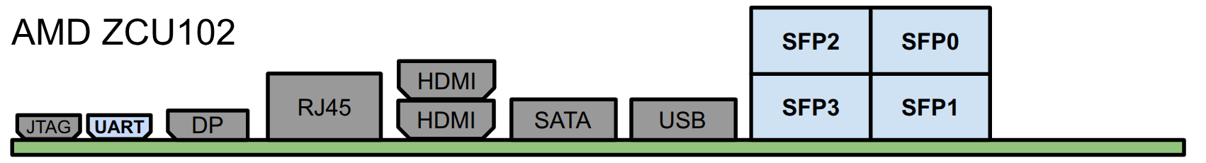
Figure 1.2 SFP Locations on the zcu102.
1.1.1. ERD 0 (2x1G)
NPAP Instance |
ETH Link |
MAC Clock |
Netperf |
TCP User Sns |
UDP User Sns |
IPv4 Address |
SFP Port No |
|---|---|---|---|---|---|---|---|
1 |
1G |
Sync |
yes |
4 |
4 |
192.168.0.1 |
SFP2 |
2 |
1G |
Async |
yes |
4 |
4 |
192.168.0.2 |
SFP3 |
- Additional ERD specifics:
TCP Buffer Sizes of 64 KiB
UDP Buffer Sizes of 64 KiB
1.1.2. ERD 1 (1x10G)
NPAP Instance |
ETH Link |
MAC Clock |
Netperf |
TCP User Sns |
UDP User Sns |
IPv4 Address |
SFP Port No |
|---|---|---|---|---|---|---|---|
1 |
10G |
Sync |
yes |
8 |
1 |
192.168.1.1 |
SFP0 |
ERD 1 Block Diagram

Figure 1.3 Block Diagram showing available blocks on the ERD 1.
1.1.3. ERD 100 (1x10G)
NPAP Instance |
ETH Link |
MAC Clock |
Netperf |
TCP User Sns |
UDP User Sns |
IPv4 Address |
SFP Port No |
|---|---|---|---|---|---|---|---|
1 |
10G |
Async |
yes |
4 |
1 |
192.168.100.1 |
SFP0 |
ERD 100 Block Diagram

Figure 1.4 Block Diagram showing the hybrid design of the ERD 100.
- Additional ERD specifics:
Hybrid acceleration design integrating NPAP within the open-source Corundum NIC.
Traffic is split at the Ethernet layer based on the destination MAC address to completely isolate hardware-accelerated (NPAP) and software-managed (Linux) TCP/IP stacks.
Network Impairment Generator is disabled
read PS output via the UART port (Micro-USB) or connect to it via ssh over the RJ45 connector
1.1.4. ERD 101 (1x10G)
NPAP Instance |
ETH Link |
MAC Clock |
Netperf |
TCP User Sns |
UDP User Sns |
IPv4 Address |
SFP Port No |
|---|---|---|---|---|---|---|---|
1 |
10G |
Sync |
no |
0 |
5 |
192.168.101.1 |
SFP0 |
1.2. ERDs on MLE NPAC Ketch
Board Overview
SoC: Intel Stratix 10 GX 400
Board Vendor: MLE
Product Page: MLE NPAP Overview
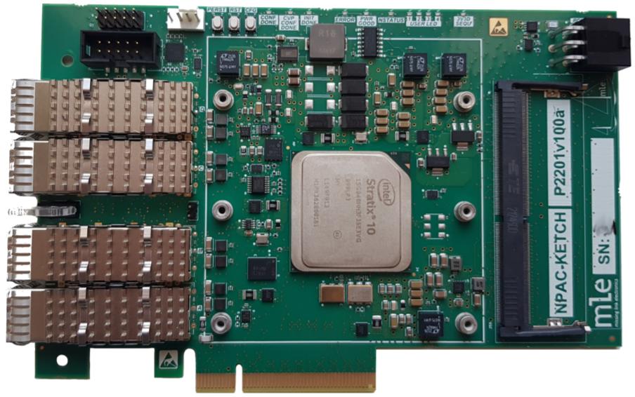
Figure 1.5 MLE NPAC-KETCH SmartNIC (figure from the MLE NPAP Overview)
We currently offer two ERDs for the NPAC Ketch board: ERD 2 (2x10G) and ERD 4 (1x40G). In both ERDs: control via NPAP HAL is possible via the USB JTAG/UART Micro-USB B on the NPAC Ketch board. Figure 1.6 shows the SFP ports of the NPAC Ketch board, which are referenced in the ERD overview tables.
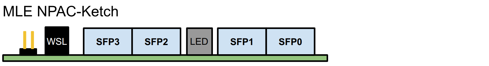
Figure 1.6 SFP port location on the NPAC Ketch board.
1.2.1. ERD 2 (2x10G)
NPAP Instance |
ETH Link |
MAC Clock |
Netperf |
TCP User Sns |
UDP User Sns |
IPv4 Address |
SFP Port No |
|---|---|---|---|---|---|---|---|
1 |
10G |
Async |
yes |
1 |
1 |
192.168.2.1 |
SFP0 |
2 |
10G |
Async |
yes |
1 |
1 |
192.168.2.2 |
SFP1 |
1.2.2. ERD 4 (1x40G)
Note
This ERD is planned for a future release, meaning active development has not yet started.
NPAP Instance |
ETH Link |
MAC Clock |
Netperf |
TCP User Sns |
UDP User Sns |
IPv4 Address |
SFP Port No |
|---|---|---|---|---|---|---|---|
1 |
40G |
Async |
yes |
1 |
1 |
192.168.4.1 |
0,1,2,3 |
1.3. ERDs on AMD ZCU111
Board Overview
SoC: Zynq UltraScale+ XCZU28DR-2FFVG1517E RFSoC
Board Vendor: AMD
Product Page: AMD ZCU111 Product Page
User Guide: ZCU111 Evaluation Board User Guide (UG1271)
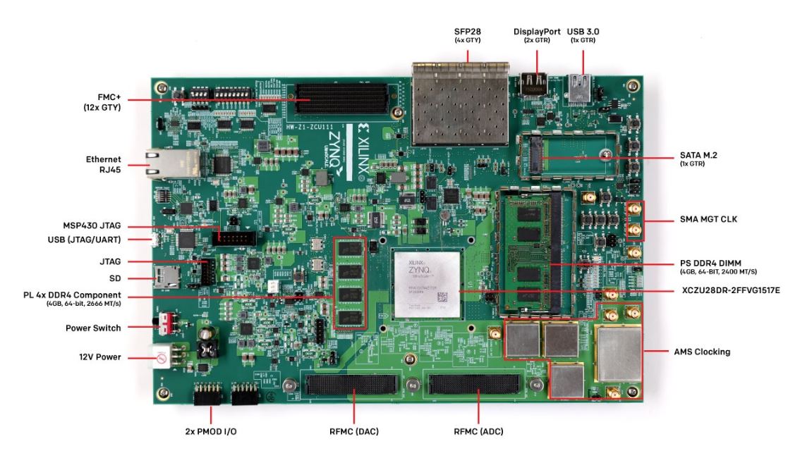
Figure 1.7 AMD ZCU111 Evaluation Board (figure from the AMD ZCU111 Product Page)
Important
The ERDs on the ZCU111 use the 322.265625 MHz clock from the SI570. So please ensure that you use our BOOT.bin, which includes a FSBL that ensures the correct clock configuration.
We currently offer three ERDs for the AMD ZCU111 evaluation board: ERD 3 (1x25G), ERD 5 (1x100G) and ERD 14 (2x10G). In all three ERDs: control via NPAP HAL is possible via the USB UART port on the ZCU111 shown in Figure 1.7. Figure 1.8 shows the SFP ports the ZCU111, which are referenced in the ERD overview tables.
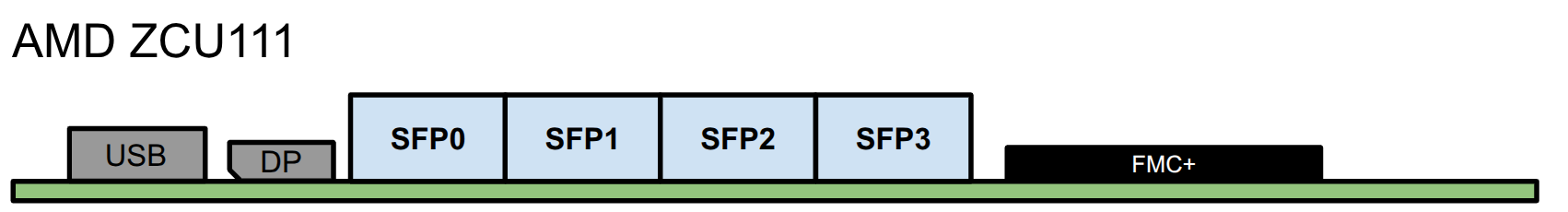
Figure 1.8 SFP port location on the ZCU111 evaluation board.
1.3.1. ERD 3 (1x25G)
NPAP Instance |
ETH Link |
MAC Clock |
Netperf |
TCP User Sns |
UDP User Sns |
IPv4 Address |
SFP Port No |
|---|---|---|---|---|---|---|---|
1 |
25G |
Async |
yes |
5 |
1 |
192.168.3.1 |
SFP0 |
- Additional ERD specifics:
TCP Buffer Sizes of 256 KiB
1.3.2. ERD 5 (1x100G)
NPAP Instance |
ETH Link |
MAC Clock |
Netperf |
TCP User Sns |
UDP User Sns |
IPv4 Address |
SFP Port No |
|---|---|---|---|---|---|---|---|
1 |
100G |
Sync |
yes |
3 |
1 |
192.168.5.1 |
SFP0,SFP1 SFP2,SFP3 |
- Additional ERD specifics:
TCP Buffer Sizes of 256 KiB
1.3.3. ERD 14 (2x10G)
NPAP Instance |
ETH Link |
MAC Clock |
Netperf |
TCP User Sns |
UDP User Sns |
IPv4 Address |
SFP Port No |
|---|---|---|---|---|---|---|---|
1 |
10G |
Async |
yes |
5 |
1 |
192.168.14.1 |
SFP0 |
2 |
10G |
Sync |
yes |
5 |
1 |
192.168.14.2 |
SFP1 |
1.4. ERD 7 on Microchip MPF300
Board Overview
SoC: 300K LE PolarFire FPGA (MPF300TS-1FCG1152I)
Board Vendor: Microchip
Product Page: MPF300 Eval Kit Product Page
User Guide: PolarFire FPGA Evaluation Kit User Guide (UG0747)
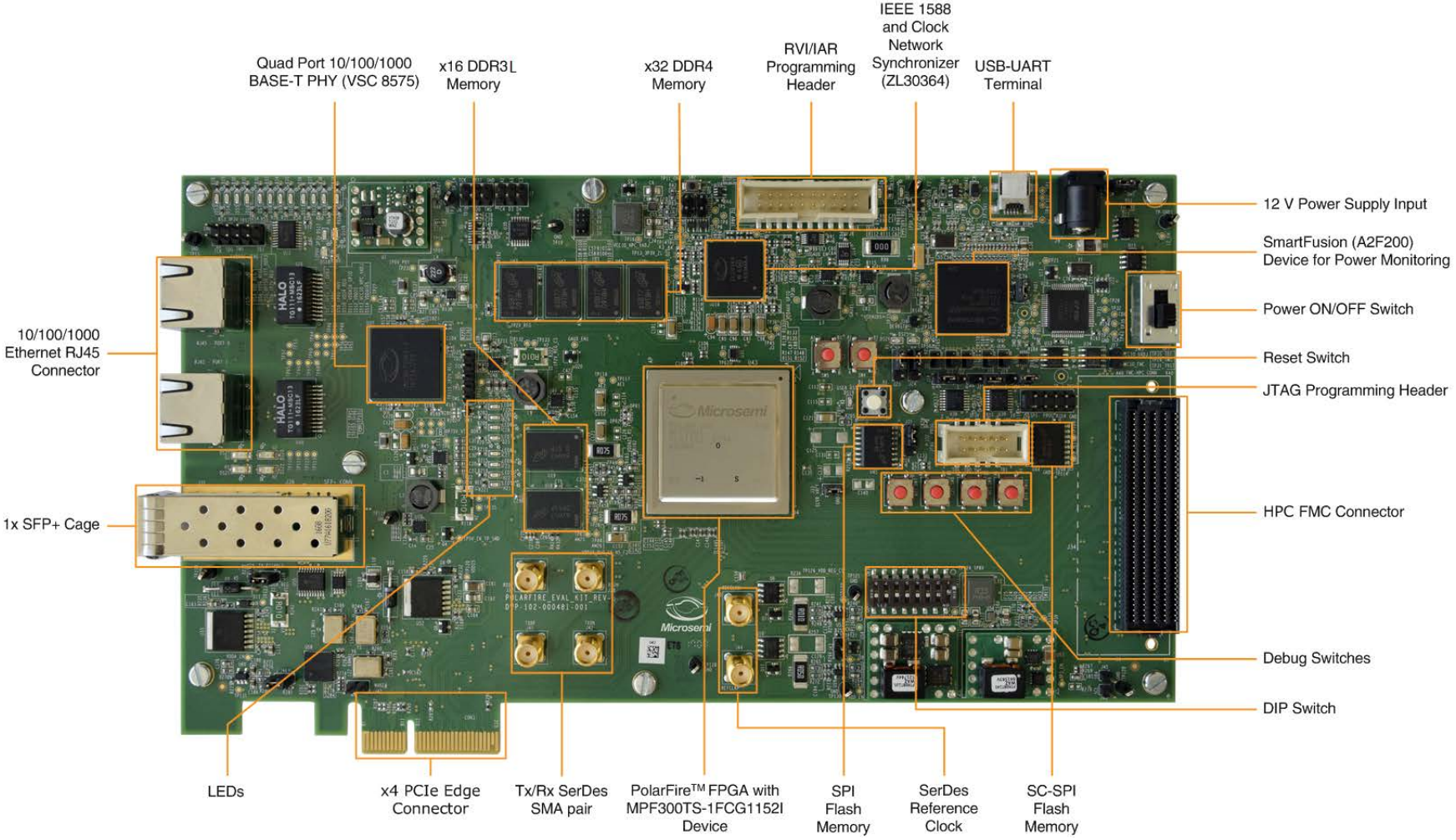
Figure 1.9 Microchip PolarFire Evaluation Kit (figure from Mouser Electronics)
The ERD 7 supports control via NPAP HAL via the port marked USB-UART Terminal in Figure 1.9. Figure 1.10 shows the SFP port of the MPF300, which are referenced in the ERD overview table.
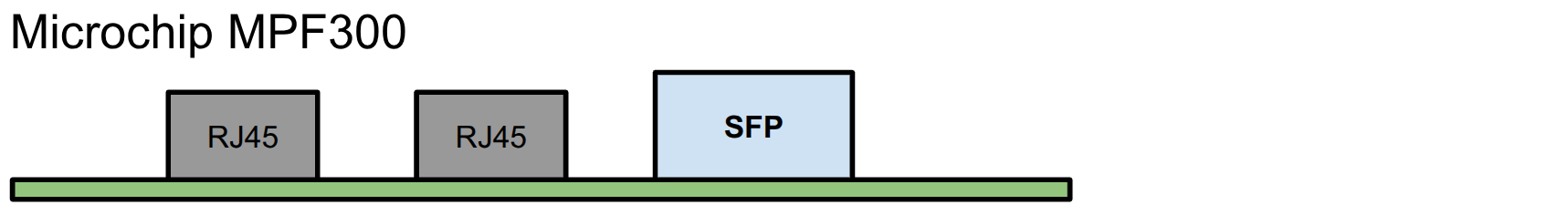
Figure 1.10 SFP port location on the Microchip PolarFire Evaluation Kit.
1.4.1. ERD 7 (1x10G)
NPAP Instance |
ETH Link |
MAC Clock |
Netperf |
TCP User Sns |
UDP User Sns |
IPv4 Address |
SFP Port No |
|---|---|---|---|---|---|---|---|
1 |
10G |
Sync |
yes |
2 |
1 |
192.168.7.1 |
0 |
- Additional ERD specifics:
instanciates the Microchip MAC
1.5. ERD 8 Trenz TE0950
Board Overview
SoC: AMD Versal™ AI Edge XCVE2302-1LSESFVA784
Board Vendor: Trenz Electronic
Product Page: TE0950 Product Page
User Guide: TE0950 Technical Reference Manual
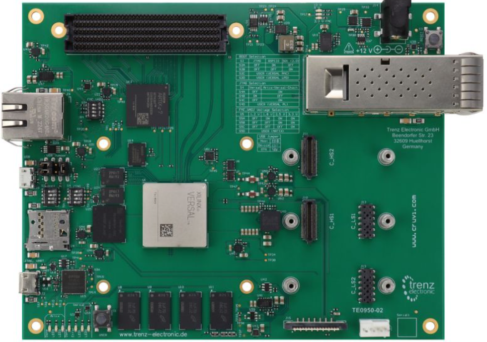
Figure 1.11 Trenz Electronic TE0950 Evaluation Board. (figure from TE0950 Product Page)
The ERD 8 supports control via NPAP HAL via the USB JTAG/UART Micro-USB B interface detailed in the TE0950 User Guide. Figure 1.12 shows the QSFP port location on the TE0950, , which are referenced in the ERD overview table.

Figure 1.12 SFP port location on the TE0950 Evaluation Board.
1.5.1. ERD 8 (1x25G)
NPAP Instance |
ETH Link |
MAC Clock |
Netperf |
TCP User Sns |
UDP User Sns |
IPv4 Address |
SFP Port No |
|---|---|---|---|---|---|---|---|
1 |
25G |
Async |
yes |
2 |
1 |
192.168.8.1 |
QSFP0:0 |
- Additional ERD specifics:
TCP Buffer Sizes of 256 KiB
1.6. ERD 10 on AMD Alveo U200
Board Overview
Note
This board is not produced by AMD anymore, AMD recommends new designs to target the Alveo V80 card. An ERD for the V80 is currently in development and available under early access.
SoC: UltraScale+ XCU200-2FSGD2104E
Board Vendor: AMD
Product Page: AMD Alveo U200 Product Page
User Guide: Alveo U200 and U250 Accelerator Cards User Guide (UG1289)
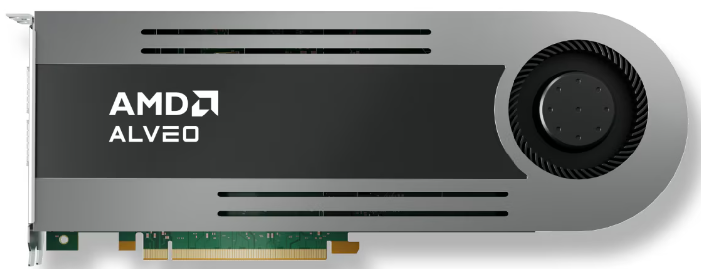
Figure 1.13 AMD Alveo U200 (figure from AMD Alveo U200 Product Page)
The ERD 10 supports control via NPAP HAL via the USB JTAG/UART Micro-USB interface on the U200. Figure 1.14 shows the QSFP ports and the UART Micro-USB port on the U200, , which are referenced in the ERD overview table.

Figure 1.14 SFP port location on the AMD Alveo U200.
1.6.1. ERD 10 (1x25G)
NPAP Instance |
ETH Link |
MAC Clock |
Netperf |
TCP User Sns |
UDP User Sns |
IPv4 Address |
SFP Port No |
|---|---|---|---|---|---|---|---|
1 |
25G |
Async |
yes |
5 |
2 |
192.168.10.1 |
QSFP1:0 |
- Additional ERD specifics:
TCP Buffer Sizes of 256 KiB
1.7. ERD 11 on AMD Alveo U55C
Board Overview
SoC: UltraScale+ XCU55C FPGA
Board Vendor: AMD
Product Page: AMD Alveo U55C Product Page
User Guide: Alveo U55C Data Center Accelerator Card User Guide (UG1469)
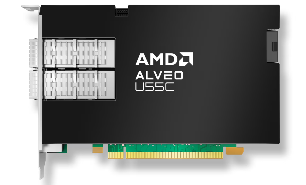
Figure 1.15 AMD Alveo U55C (figure from AMD Alveo U55C Product Page)
The ERD 11 supports control via NPAP HAL via the USB JTAG/UART Micro-USB interface on the U55C. Figure 1.16 shows the QSFP ports and the UART Micro-USB port on the U55C, which are referenced in the ERD overview tables.

Figure 1.16 SFP port location on the AMD Alveo U55C.
1.7.1. ERD 11 (4x25G)
NPAP Instance |
ETH Link |
MAC Clock |
Netperf |
TCP User Sns |
UDP User Sns |
IPv4 Address |
SFP Port No |
|---|---|---|---|---|---|---|---|
1 |
25G |
Async |
yes |
1 |
1 |
192.168.11.1 |
QSFP0:0 |
2 |
25G |
Async |
yes |
1 |
1 |
192.168.11.2 |
QSFP0:1 |
3 |
25G |
Async |
yes |
1 |
1 |
192.168.11.3 |
QSFP0:2 |
4 |
25G |
Async |
yes |
1 |
1 |
192.168.11.4 |
QSFP0:3 |
- Additional ERD specifics:
TCP Buffer Sizes of 256 KiB
1.8. ERD 12 on Lattice Avant-G
Board Overview
SoC: Avant-G 500 LC FPGA (LAV-AT-G70-3LFG1156I)
Board Vendor: Lattice
Product Page: Avant-G Product Page
User Guide: Avant-G/X Versa Board User Guide
Note
To program a bitfile via JTAG please ensure that jumper JP1 is correctly configured.
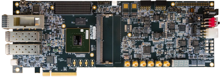
Figure 1.17 Lattice Avant-G Evaluation Board: (figure from Avant-G Product Page)
The ERD 12 supports control via NPAP HAL via the USB JTAG/UART Micro-USB interface on the Avant-G board. Figure 1.16 shows the SFP port locations on the Avant-G, which are referenced in the ERD overview table.

Figure 1.18 SFP port location on the Avant-G Evaluation Board.
1.8.1. ERD 12 (1x10G)
NPAP Instance |
ETH Link |
MAC Clock |
Netperf |
TCP User Sns |
UDP User Sns |
IPv4 Address |
SFP Port No |
|---|---|---|---|---|---|---|---|
1 |
10G |
Sync |
yes |
1 |
1 |
192.168.12.1 |
SFP0 |
- Additional ERD specifics:
Lattice 10G Ethernet IP Core is used as MAC
1.9. ERD 13 on Arrow Agilex 5 Eagle
Board Overview
SoC: Intel Agilex® 5 E-series SoC FPGA (A5E 043B-434 kLE)
Board Vendor: Intel
Product Page: Agilex 5 Eagle Product Page
User Guide: AXE5-Eagle User Guide
Figure 1.19 Arrow Agilex 5 Eagle Development Kit (figure from Agilex 5 Eagle Product Page)
The ERD 13 supports control via NPAP HAL via the USB JTAG/UART Micro-USB interface on the Agilex-5e board. Figure 1.20 shows the SFP port locations on the Avant-G, which are referenced in the ERD overview table.
Figure 1.20 SFP port location on the Arrow Agilex 5 Eagle Development Kit.
1.9.1. ERD 13 (1x10G)
NPAP Instance |
ETH Link |
MAC Clock |
Netperf |
TCP User Sns |
UDP User Sns |
IPv4 Address |
SFP Port No |
|---|---|---|---|---|---|---|---|
1 |
10G |
Async |
yes |
5 |
3 |
192.168.13.1 |
0 |
- Additional ERD specifics:
Altera 10G Ethernet IP is used as MAC
1.10. ERD 15 on Avnet Tria AUB15P
Board Overview
SoC: AMD Artix UltraScale+ 15P (XCAU15P-2FFVB676E)
Board Vendor: AMD
Product Page: AUB15P Product Page
User Guide: AUBoard-15P Development Kit Hardware User Guide
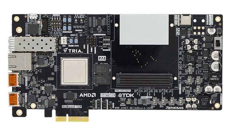
Figure 1.21 Avnet Tria AUB15P Development Kit (figure from AUB15P Product Page)
The ERD 15 supports control via NPAP HAL via the USB JTAG/UART Micro-USB interface on the AUB15P board. Figure 1.22 shows the location of the AUB15P’s SFP port, which are referenced in the ERD overview table.

Figure 1.22 SFP port location on the Avnet Tria AUB15P Development Kit.
1.10.1. ERD 15 (1x10G)
NPAP Instance |
ETH Link |
MAC Clock |
Netperf |
TCP User Sns |
UDP User Sns |
IPv4 Address |
SFP Port No |
|---|---|---|---|---|---|---|---|
1 |
10G |
Sync |
yes |
1 |
1 |
192.168.15.1 |
0 |
- Additional ERD specifics:
reduced UDP buffer sizes of 4 KiB
reduced TCP buffer sizes of 64 KiB
For the design to work the following jumper settings need to be applied:
Remove Jumpers J15, J16, J17 (SFP configurations)
Attach jumper to J11 connecting PIN1 and PIN2 (for FPGA only JTAG chain)
Attach jumper to J46 (voltage select header)