Quickstart Guide
The objective of this Quickstart Guide is to give you a quick introduction into the various deliverables of ZU19SN and describe how to run these. Think of this as a collection of user guides.
The following sections provide a quick start into getting the Sidewinder-100 board itself and various reference designs up and running.

Fig. 1 Sidewinder-100 Board Components.
Board Bringup
Please follow these steps to connect and power up the Sidewinder-100 board as shown in Fig. 1:
Note
There are two modes of operation for the Sidewinder-100:
- PCIe ×16 endpoint connector powered by a host PC.
- PCIe ×16 endpoint connector powered by a dedicated power supply board provided by Fidus.
In either case the 6-pin ATX PCIe power connector must be powered as well for the board to come out of reset.
Insert the PCIe ×16 endpoint connector into a free PCIe slot of the host PC while it is powered off,
or
Insert the PCIe ×16 endpoint connector into the dedicated power supply board provided by Fidus.
Connect the 6-pin PCIe power connector with the ATX power supply of the host PC.
Connect the JTAG connector J104 with your JTAG cable according to the pin assignment of Fig. 2.
The board can now be powered up by booting the host PC. Make sure that all power rail status LEDs according to Fig. 3 turn green.
You should now be able to connect to the Zynq UltraScale+ FPGA on the board via JTAG and upload a bitstream.

Fig. 2 JTAG Connector Pin Assignment. Numbers in braces denote callout in Fig. 8.

Fig. 3 Status LEDs.
PetaLinux
MLE has put together a Linux runtime environment, based on Xilinx PetaLinux 2016.4 and optimized for the Sidewinder-100 board. Please follow these steps to boot a pre-built PetaLinux environment from SD card:
Download the Software Reference Project from MLE. Please contact MLE for download instructions.
Extract the tarball on your disk and enter the extracted folder.
Prepare a SD card with a MBR partition table comprising a single, bootable FAT32 partition.
Copy the pre-built files
BOOT.BINandimage.ubfrompre-built/linux/imagesof the Software Reference Project onto the SD card FAT32 partition.Insert the SD card into the card holder of the Sidewinder-100 board.
Set the boot mode DIP switch SW5 to SD card (off, on, off, on) as shown in Fig. 4.
Connect the USB to UART port J33 on the Sidewinder-100 board with your development host.
Start up a terminal emulator (e.g. Minicom, PuTTY or Tera Term). You should see two serial devices on your board; connect to the first one (e.g.
/dev/ttyUSB0under Linux) with baud rate 115200, data bits 8, stop bits 1, no parity and no flow control.If you would like to access the board remotely via Ethernet, connect the off-board RJ45 connector adapter cable with pin header J117 on the board. Make sure the cable is correctly aligned by pointing it towards the PCIe ×8 host connector, away from the board.
The board can now be powered up by booting the host PC. Make sure that all power rail status LEDs according to Fig. 3 turn green. PS INIT should turn from red to green and PS DONE should light up as soon as the FPGA bitstream has been loaded by the FSBL.
You should see the FSBL, PMU firmware, ARM Trusted Firmware, U-Boot and finally Linux booting up in your terminal emulator:
Xilinx Zynq MP First Stage Boot Loader
Release 2016.4   Jul 11 2017  -  16:41:17
XPFW: Calling ROM PWRUP Handler..Done
XPFW: Calling ROM Isolation Handler..Done
XPFW: Calling ROM PWRUP Handler..Done
PMUFW: PmInit:
...
 ATF running on XCZU19EG/silicon v3/RTL5.1 at 0xfffea000, with PMU firmware
NOTICE:  BL31: Secure code at 0x0
NOTICE:  BL31: Non secure code at 0x8000000
NOTICE:  BL31: v1.3(release):1bb0730
NOTICE:  BL31: Built : 16:34:48, Jul 11 2017


U-Boot 2016.07 (Jul 11 2017 - 16:41:30 +0200) Xilinx ZynqMP ZCU102 revB

DRAM:  16 GiB
EL Level: EL2
Chip ID:  xczu19eg
MMC:   sdhci@ff170000: 0
SF: Detected N25Q1024 with page size 512 Bytes, erase size 8 KiB, total 256 MiB
In:    serial
Out:   serial
Err:   serial
Net:   ZYNQ GEM: ff0e0000, phyaddr -1, interface rgmii-id
eth0: ethernet@ff0e0000
U-BOOT for

ethernet@ff0e0000 Waiting for PHY auto negotiation to complete..... done
BOOTP broadcast 1
BOOTP broadcast 2
DHCP client bound to address 10.89.231.254 (254 ms)
Hit any key to stop autoboot:  4 3 2 1 0
Device: sdhci@ff170000
Manufacturer ID: 3
OEM: 5344
Name: SU08G
Tran Speed: 50000000
Rd Block Len: 512
SD version 3.0
High Capacity: Yes
Capacity: 7.4 GiB
Bus Width: 4-bit
Erase Group Size: 512 Bytes
reading image.ub
19579820 bytes read in 1295 ms (14.4 MiB/s)
## Loading kernel from FIT Image at 10000000 ...
   Using 'conf@1' configuration
   Trying 'kernel@0' kernel subimage
   ...
   Loading Kernel Image ... OK
   Loading Ramdisk to 0790d000, end 07fffa23 ... OK
   Loading Device Tree to 0000000007903000, end 000000000790cf0c ... OK

Starting kernel ...

[    0.000000] Booting Linux on physical CPU 0x0
[    0.000000] Linux version 4.6.0-xilinx (stefan@napf) (gcc version 5.2.1 20151005 (Linaro GCC 5.2-2015.11-2) ) #1 SMP Tue Jul 11 16:40:10 CEST 2017
[    0.000000] Boot CPU: AArch64 Processor [410fd034]
[    0.000000] earlycon: cdns0 at MMIO 0x00000000ff000000 (options '115200n8')
[    0.000000] bootconsole [cdns0] enabled
...
Hint
If U-Boot fails to boot the Linux kernel, the QSPI flash might hold ill-suited environment settings from a previous installation. From the U-Boot prompt, execute:
ZynqMP> env default -a
ZynqMP> env save
and then proceed with booting the Linux kernel:
ZynqMP> boot
As soon as the login prompt appears, you can sign in using username
rootand passwordroot.Note
The following warning message from the Xen Linux kernel driver will appear periodically on the serial console:
INIT: Id "X0" respawning too fast: disabled for 5 minutes
It can be safely ignored and will be fixed in a future release.

Fig. 4 Boot Mode DIP switch set to SD card.
10/25 GbE MAC Loopback Example Design
This section describes how to connect and how to run the 10/25 GbE MAC Loopback Example Design. The objective of this design is to test and try 10/25 GbE connectivity between the ZU19SN and a PC or server.
The two 10 GbE MAC and 25 GbE MAC Loopback example designs provide MAC layer connectivity and loopback for 10 GBit/s Ethernet and 25 GBit/s Ethernet respecitvely. This means an Ethernet frame can be sent from a host to the board an it is looped back to the host without touching the frame data. This section is about using the 10 GbE and 25 GbE MAC Loopback example design. When material, handling or commands as well as ouptput differ, both are displayed beginning with the 10 GbE variant. For SD card image and bitfile generation see 10/25 GbE MAC Loopback Example Design.
In order to test the example design some additional parts other than the board are needed:
- QSFP+ to SFP+ connectivity supporting the needed speeds (10 GbE: QSFP+/ SFP+, 25 GbE: QSFP28/SFP28) , e.g. via
- QSFP to SFP adapter and an SFP+ cable
- 1x QSFP to 4x SFP breakout cable assembly including QSFP and SFP connectors, e.g. a DAC copper twinax cable assembly
- A host equipped with
- a NIC (10 GbE NIC for 10 GbE or 25 GbE NIC for both 10 GbE or 25 GbE)
- running a Linux OS (needed for closely following this tutorial), e.g. Ubuntu 14.4
- having Wireshark and ethtool installed.
The example design uses the boards QSFP0 connector for Ethernet connectivity, see callout number 10 in Table 1 and Fig. 8.
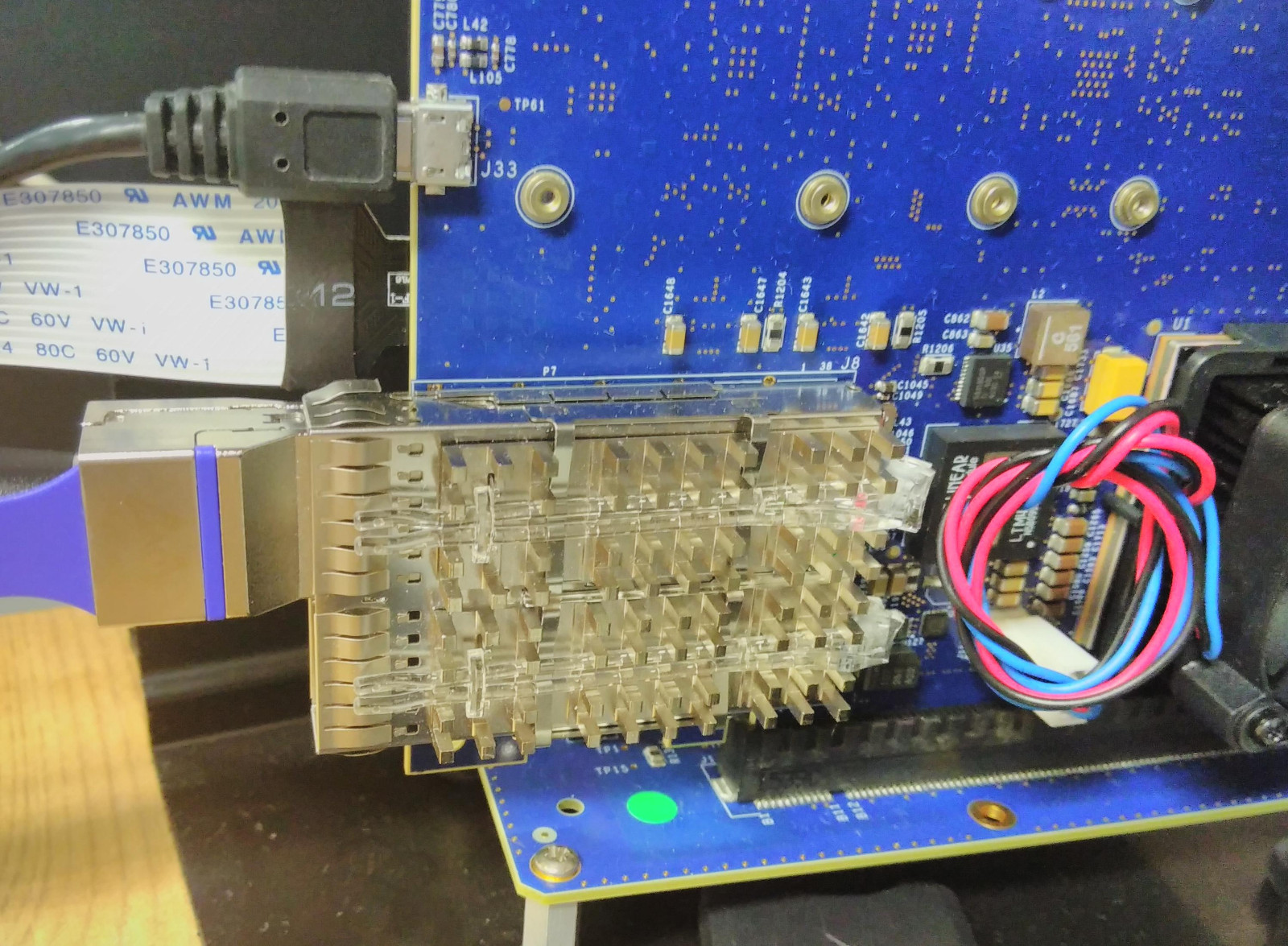
Fig. 5 QSFP28 copper cable attached to the board
The setup of the board for this reference design is shown in Fig. 5. It uses a 40 GbE (100 GbE) to 10 GbE (25 GbE) twinax copper breakout cable, such as a Mellanox MCP7F00-A001 cable assembly (1x QSFP28 to 4x SFP28) for both 10 GbE and 25 GbE. Please make sure to connect the first lane of QSFP28 connectors to the PC, which is usually markes on the breakout cables. Alternatively a Mellanox MAM1W00A-QSA QSFP+ to SFP+ converter may be used to connect a single 10 GbE SFP+ adapter into the 40 GbE QSFP+ sockets on the board for 10 GbE. The board is directly connected to the host without any switches or routers in between.
Note
Please note that in order to use the QSFP28 Ethernet connectors present on the board, the power supply for these interfaces need to be switched on by software running on the PS. So it is necessary to use some piece of software to switch it on initially. This is taken care of by the PetaLinux system provided along with this example design, see PetaLinux. Afterwards you may reconfigure the FPGA part.
The standard host PC used in the demo is equipped with a dual ported intel X520-2 10 GbE network interface card (NIC) for 10 GbE tests and a Mellanox ConnectX 4 LX (MT27630 Family) 25 GbE single port NIC.
The host runs a standard Linux system, e.g. Ubuntu 14.04.
The IP address of the connected network interface (in our case eth2) is set to 192.168.2.12.
Ip addresses may be changed using the ifconfig command via the command line with superuser rights:
sudo ifconfig eth2 192.168.2.12.
Note
The interface and IP addresses might need adjustments in your setup, so please check carefully to use the right ethernet port and associate an IP address with it which does not interfere with your hosts other interfaces. You may also need to adapt the commands within the guide to your settings.
Please make sure you installed Wireshark and its dependencies, e.g. via the Linux distributions package management system, e.g. apt.
When the board is wired up and starting with this example designs SD card image, the Ethernet connectivity is checked regularly by calling ifconfig and ethtool (10 GbE):
# watch -n 0.5 sudo "ethtool eth2 ; echo "" ; sudo ifconfig eth2; echo ""; sudo ethtool -S eth2 | grep x_packets"

Every 0.5s: sudo ethtool eth2 ; echo  ; sudo ifconfig eth2; echo ; sudo ethtool -S eth2 | grep x_packets

Settings for eth2:
        Supported ports: [ FIBRE ]
        Supported link modes:   10000baseT/Full
        Supported pause frame use: No
        Supports auto-negotiation: No
        Advertised link modes:  10000baseT/Full
        Advertised pause frame use: Symmetric
        Advertised auto-negotiation: No
        Speed: 10000Mb/s
        Duplex: Full
        Port: Direct Attach Copper
        PHYAD: 0
        Transceiver: external
        Auto-negotiation: off
        Supports Wake-on: d
        Wake-on: d
        Current message level: 0x00000007 (7)
                              drv probe link
        Link detected: yes

eth2      Link encap:Ethernet  HWaddr 90:e2:ba:4a:d9:ad
          inet addr:192.168.2.12  Bcast:192.168.2.255  Mask:255.255.255.0
          inet6 addr: fe80::92e2:baff:fe4a:d9ad/64 Scope:Link
          UP BROADCAST RUNNING MULTICAST  MTU:1500  Metric:1
          RX packets:608 errors:2 dropped:0 overruns:0 frame:2
          TX packets:3215 errors:0 dropped:0 overruns:0 carrier:0
          collisions:0 txqueuelen:1000
          RX bytes:135015 (135.0 KB)  TX bytes:352322 (352.3 KB)


    rx_packets: 608
    tx_packets: 3215
(25 GbE):
Settings for eth6:
    Supported ports: [ FIBRE ]
    Supported link modes:   1000baseT/Full
                            1000baseKX/Full
                            10000baseKR/Full
    Supported pause frame use: Symmetric Receive-only
    Supports auto-negotiation: Yes
    Advertised link modes:  1000baseT/Full
                            1000baseKX/Full
                            10000baseKR/Full
    Advertised pause frame use: No
    Advertised auto-negotiation: Yes
    Speed: 25000Mb/s
    Duplex: Full
    Port: Other
    PHYAD: 0
    Transceiver: internal
    Auto-negotiation: on
    Supports Wake-on: d
    Wake-on: d
    Current message level: 0x00000004 (4)
                           link
    Link detected: yes

eth6      Link encap:Ethernet  HWaddr 24:8a:07:17:a3:90
          inet addr:192.168.200.1  Bcast:192.168.200.255  Mask:255.255.255.0
          inet6 addr: fe80::268a:7ff:fe17:a390/64 Scope:Link
          UP BROADCAST RUNNING MULTICAST  MTU:1500  Metric:1
          RX packets:201 errors:0 dropped:0 overruns:0 frame:0
          TX packets:201 errors:0 dropped:0 overruns:0 carrier:0
          collisions:0 txqueuelen:1000
          RX bytes:31011 (31.0 KB)  TX bytes:32111 (32.1 KB)


    rx_packets: 201
    tx_packets: 201
    tx_packets_phy: 201
    rx_packets_phy: 201
Note
The Ubuntu 14.04 ethtool apparantly is not capable of decoding the speed Advertisement of 25000Mb/s, but correctly displays the actual link speed as 25000Mb/s.
When the physical Ethernet link is ready, indicated by the Link detected: yes output of ethtool, packets can be send to the board and the looped back ones sniffed via Wireshark.
Wireshark is a widely used network traffic analysis tool, which is available for Linux and Windows and uses libpcap to interface ethernet interfaces.
The given command immediately starts Wireshark capturing on the network interface attached to the board:
sudo wireshark -i eth2 -k &
Then we will ping any IP within the network associated with the hosts Ethernet port the Fidus board is connected to:
# ping 192.168.2.11
PING 192.168.2.11 (192.168.2.11) 56(84) bytes of data.
From 192.168.2.12 icmp_seq=1 Destination Host Unreachable
From 192.168.2.12 icmp_seq=2 Destination Host Unreachable
From 192.168.2.12 icmp_seq=3 Destination Host Unreachable
From 192.168.2.12 icmp_seq=4 Destination Host Unreachable
From 192.168.2.12 icmp_seq=5 Destination Host Unreachable
From 192.168.2.12 icmp_seq=6 Destination Host Unreachable
The IP cannot be reached as the board does not implement the corresponding protocol. However, the Ethernet frames sent by the host to discover the IP (ARP requests) are looped back by the board. These are then both captured and displayed by Wireshark, see Fig. 6. The original frame sent by the host is shown as packet #1 and the looped back packet is shown as packet #2.
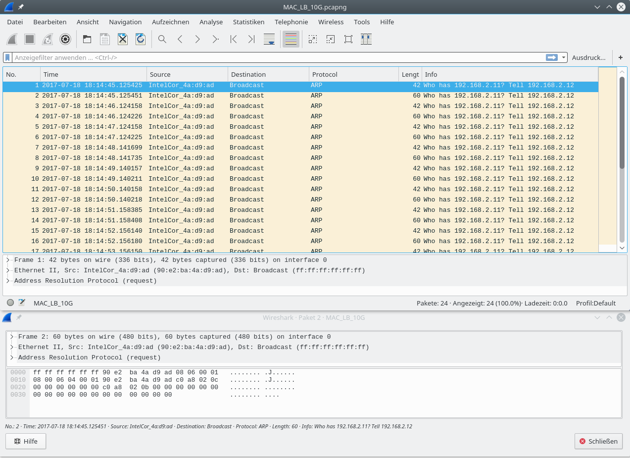
Fig. 6 Wireshark showing the original (#1) and looped back packet (#2)
Also the output of the command initially used to check physical connectivity between host and board reports transmitted packets. Note the changed numbers of transmitted and received packets in the last two lines (10 GbE):
# watch -n 0.5 sudo "ethtool eth2 ; echo "" ; sudo ifconfig eth2; echo ""; sudo ethtool -S eth2 | grep x_packets"

Settings for eth2:
        Supported ports: [ FIBRE ]
        Supported link modes:   10000baseT/Full
        Supported pause frame use: No
        Supports auto-negotiation: No
        Advertised link modes:  10000baseT/Full
        Advertised pause frame use: Symmetric
        Advertised auto-negotiation: No
        Speed: 10000Mb/s
        Duplex: Full
        Port: Direct Attach Copper
        PHYAD: 0
        Transceiver: external
        Auto-negotiation: off
        Supports Wake-on: d
        Wake-on: d
        Current message level: 0x00000007 (7)
                              drv probe link
        Link detected: yes

eth2      Link encap:Ethernet  HWaddr 90:e2:ba:4a:d9:ad
          inet addr:192.168.2.12  Bcast:192.168.2.255  Mask:255.255.255.0
          inet6 addr: fe80::92e2:baff:fe4a:d9ad/64 Scope:Link
          UP BROADCAST RUNNING MULTICAST  MTU:1500  Metric:1
          RX packets:620 errors:2 dropped:0 overruns:0 frame:2
          TX packets:3227 errors:0 dropped:0 overruns:0 carrier:0
          collisions:0 txqueuelen:1000
          RX bytes:135735 (135.7 KB)  TX bytes:352826 (352.8 KB)


    rx_packets: 620
    tx_packets: 3227
(25 GbE):
# watch -n 0.5 sudo "ethtool eth6 ; echo "" ; sudo ifconfig eth6; echo ""; sudo ethtool -S eth6 | grep x_packets"

Settings for eth6:
        Supported ports: [ FIBRE ]
        Supported link modes:   1000baseT/Full
                                1000baseKX/Full
                                10000baseKR/Full
        Supported pause frame use: Symmetric Receive-only
        Supports auto-negotiation: Yes
        Advertised link modes:  1000baseT/Full
                                1000baseKX/Full
                                10000baseKR/Full
        Advertised pause frame use: No
        Advertised auto-negotiation: Yes
        Speed: 25000Mb/s
        Duplex: Full
        Port: Other
        PHYAD: 0
        Transceiver: internal
        Auto-negotiation: on
        Supports Wake-on: d
        Wake-on: d
        Current message level: 0x00000004 (4)
                              link
        Link detected: yes

eth2      Link encap:Ethernet  HWaddr 90:e2:ba:4a:d9:ad
          inet addr:192.168.200.1  Bcast:192.168.200.255  Mask:255.255.255.0
          inet6 addr: fe80::92e2:baff:fe4a:d9ad/64 Scope:Link
          UP BROADCAST RUNNING MULTICAST  MTU:1500  Metric:1
          RX packets:253 errors:0 dropped:0 overruns:0 frame:2
          TX packets:253 errors:0 dropped:0 overruns:0 carrier:0
          collisions:0 txqueuelen:1000
          RX bytes:135735 (135.7 KB)  TX bytes:352826 (352.8 KB)


    rx_packets: 253
    tx_packets: 253
    tx_packets_phy: 253
    rx_packets_phy: 253
For further information about how to build the example design and how the information is presented within the FPGA see 10/25 GbE MAC Loopback Example Design.
PCIe Endpoint Example Design
This section describes how to connect and how to run the PCIe Endpoint Example Design. The objective of this design is to test and try PCIe connectivity between the ZU19SN and a PC or server (host computer). Here a host computer connects via PCIe to the attached Fidus Sidewinder card as an PCIe endpoint.
The provided design is a very straight forward and simple design and focuses on the demonstration of the physical connectivity of PCIe Gen3 x16. The performance will not be reached as it currently does not support PCIe endpoint DMA engines to access to transfer data to and from the board.
In order to test the example design in addition to the Fidus Sidewinder board, a host PC running Linux, e.g. Ubuntu 16.04 is needed. The board needs to be properly inserted into a mechanically fitting PCIe Slot providing 16 lanes and the additional PCIe power supply connected. You may use the pre-built SD Card images to go through this test. Switch on the PC, so that the board gets configured and wait until the operating system is started. Then reboot the PC. This step is needed as the time needed by the FPGA to fetch the images from the SD card and configure itself is longer than most BIOSs allow PCIe devices to use for initialization. When the PC is restarted, the PCIe endpoint implemented in the FPGA shows up in the PCIe hierarchy, read out by the Linux util lspci:
# sudo lspci -vt
-[0000:00]-+-00.0  Intel Corporation Sky Lake Host Bridge/DRAM Registers
      +-01.0-[01]----00.0  Xilinx Corporation Device 9031
      +-02.0  Intel Corporation Sky Lake Integrated Graphics
      +-08.0  Intel Corporation Sky Lake Gaussian Mixture Model
      +-14.0  Intel Corporation Sunrise Point-H USB 3.0 xHCI Controller
      +-14.2  Intel Corporation Sunrise Point-H Thermal subsystem
      +-16.0  Intel Corporation Sunrise Point-H CSME HECI #1
      +-17.0  Intel Corporation Sunrise Point-H SATA controller [AHCI mode]
      +-1d.0-[02]----00.0  Realtek Semiconductor Co., Ltd. RTL8111/8168/8411 PCI Express Gigabit Ethernet Controller
      +-1f.0  Intel Corporation Sunrise Point-H LPC Controller
      +-1f.2  Intel Corporation Sunrise Point-H PMC
      +-1f.3  Intel Corporation Sunrise Point-H HD Audio
      \-1f.4  Intel Corporation Sunrise Point-H SMBus
A more detailed lspci output shows the connection via a x16 Gen3 link and exporting 3 BARs:
# sudo lspci -vvv -n -s 0000:01:0.0
  01:00.0 0580: 10ee:9031
  Subsystem: 10ee:0007
  Control: I/O+ Mem+ BusMaster+ SpecCycle- MemWINV- VGASnoop- ParErr- Stepping- SERR- FastB2B- DisINTx-
  Status: Cap+ 66MHz- UDF- FastB2B- ParErr- DEVSEL=fast >TAbort- <TAbort- <MAbort- >SERR- <PERR- INTx-
  Latency: 0, Cache Line Size: 64 bytes
  Interrupt: pin A routed to IRQ 11
  Region 0: Memory at df114000 (32-bit, non-prefetchable) [size=16K]
  Region 1: Memory at df100000 (32-bit, non-prefetchable) [size=64K]
  Region 2: Memory at df110000 (32-bit, non-prefetchable) [size=16K]
  Capabilities: [40] Power Management version 3
          Flags: PMEClk- DSI- D1- D2- AuxCurrent=0mA PME(D0-,D1-,D2-,D3hot-,D3cold-)
          Status: D0 NoSoftRst+ PME-Enable- DSel=0 DScale=0 PME-
  Capabilities: [48] MSI: Enable- Count=1/1 Maskable- 64bit+
          Address: 0000000000000000  Data: 0000
  Capabilities: [60] MSI-X: Enable- Count=33 Masked-
          Vector table: BAR=1 offset=00008000
          PBA: BAR=1 offset=00008fe0
  Capabilities: [70] Express (v2) Endpoint, MSI 00
          DevCap: MaxPayload 1024 bytes, PhantFunc 0, Latency L0s <64ns, L1 <1us
                  ExtTag+ AttnBtn- AttnInd- PwrInd- RBE+ FLReset-
          DevCtl: Report errors: Correctable- Non-Fatal- Fatal- Unsupported-
                  RlxdOrd+ ExtTag+ PhantFunc- AuxPwr- NoSnoop+
                  MaxPayload 256 bytes, MaxReadReq 512 bytes
          DevSta: CorrErr+ UncorrErr- FatalErr- UnsuppReq+ AuxPwr- TransPend-
          LnkCap: Port #0, Speed 8GT/s, Width x16, ASPM not supported, Exit Latency L0s unlimited, L1 unlimited
                  ClockPM- Surprise- LLActRep- BwNot-
          LnkCtl: ASPM Disabled; RCB 64 bytes Disabled- CommClk+
                  ExtSynch- ClockPM- AutWidDis- BWInt- AutBWInt-
          LnkSta: Speed 8GT/s, Width x16, TrErr- Train- SlotClk+ DLActive- BWMgmt- ABWMgmt-
          DevCap2: Completion Timeout: Range BC, TimeoutDis+, LTR-, OBFF Not Supported
          DevCtl2: Completion Timeout: 50us to 50ms, TimeoutDis-, LTR-, OBFF Disabled
          LnkCtl2: Target Link Speed: 8GT/s, EnterCompliance- SpeedDis-
                    Transmit Margin: Normal Operating Range, EnterModifiedCompliance- ComplianceSOS-
                    Compliance De-emphasis: -6dB
          LnkSta2: Current De-emphasis Level: -6dB, EqualizationComplete+, EqualizationPhase1+
                    EqualizationPhase2-, EqualizationPhase3-, LinkEqualizationRequest-
  Capabilities: [100 v1] Advanced Error Reporting
          UESta:  DLP- SDES- TLP- FCP- CmpltTO- CmpltAbrt- UnxCmplt- RxOF- MalfTLP- ECRC- UnsupReq- ACSViol-
          UEMsk:  DLP- SDES- TLP- FCP- CmpltTO- CmpltAbrt- UnxCmplt- RxOF- MalfTLP- ECRC- UnsupReq- ACSViol-
          UESvrt: DLP+ SDES+ TLP- FCP+ CmpltTO- CmpltAbrt- UnxCmplt- RxOF+ MalfTLP+ ECRC- UnsupReq- ACSViol-
          CESta:  RxErr- BadTLP- BadDLLP- Rollover- Timeout+ NonFatalErr+
          CEMsk:  RxErr- BadTLP- BadDLLP- Rollover- Timeout- NonFatalErr+
          AERCap: First Error Pointer: 00, GenCap- CGenEn- ChkCap- ChkEn-
  Capabilities: [1c0 v1] #19
For running the example test script you also need to have a compiler installed, e.g. gcc, to compile the pcimem, which is used by the test script pcie_ep_test.sh
To run the test, goto the host/pcie_ep folder, run the ./build.sh script to build the helper tools:
# ./build.sh
Afterwards run the PCIe endpoint testscript, pcie_ep_test.sh itself. The pcie_ep_test.sh script searches for the corresponding PCIe device and uses the pcimem tool to access the BARs of the device and runs a full read / read-write-read test on the 64k address space of each BAR:
# sudo ./pcie_ep_test.sh
PCI_DEVICE:    0000:05:00.0
PCI_VENDOR_ID: 10ee
PCI_DEVICE_ID: 9031

Testing BARs
  BAR 0 at f7c10000 of size 16384
  BAR 2 at f7c14000 of size 16384

Check BAR 0 of size 16384 using /sys/bus/pci/devices/0000:05:00.0/resource0 for pre-initialization
memory region of BAR 0 is all zeros

Check BAR 2 of size 16384 using /sys/bus/pci/devices/0000:05:00.0/resource2 for pre-initialization
memory region of BAR 2 is all zeros

Start read write test on BAR 0 at offset 0...
Write and read back on memory region of BAR 0 was successfull

Start read write test on BAR 2 at offset 0...
Write and read back on memory region of BAR 2 was successfull
Note
You might need to enforce the execution within a bash shell instead of other system shells, which is indicated e.g. by the following output:
./pcie_ep_test.sh: 48: ./pcie_ep_test.sh: Syntax error: "(" unexpected
To enforce the execution by the bash shell, use the following modified command line:
# sudo bash -c ./pcie_ep_test.sh
NPAP Example Design
The Network Protocol Accelerator Platform (NPAP) allows to build customizable solutions for TCP/IP and UDP protocol acceleration. It is based on patent pending technology from German Fraunhofer Heinrich-Hertz Institute (HHI) and supports Full Acceleration in form of stream-processing of TCP and/or UDP at 1/10/25/50 GigE line rates.
This NPAP Example Design demonstrates how the Fidus Sidewinder-100 board could be connected to an Ethernet network providing TCP/IP based services. As an example this design includes a hardware implementation of most features of the netperf v2.6 network performance test tool, see the corresponding netperf github tag.
This design provides three ways of exploring the network performance of a hardware TCP/IP implementation:
- ping the board
- use the TCP loopback via telnet or nc
- use netperf to do some benchmarking on UDP and TCP layers
In order to use the design setup the board as described in section 10/25 GbE MAC Loopback Example Design. Just use the SD Card comprising the NPAP example design. Please set the IP adress of the connected network interface according to the setting shown below:
# sudo ifconfig eth2 192.168.1.105

eth2      Link encap:Ethernet  HWaddr 90:e2:ba:4a:d9:ad
          inet addr:192.168.1.105  Bcast:192.168.2.255  Mask:255.255.255.0
          inet6 addr: fe80::92e2:baff:fe4a:d9ad/64 Scope:Link
          UP BROADCAST RUNNING MULTICAST  MTU:1500  Metric:1
          RX packets:608 errors:2 dropped:0 overruns:0 frame:2
          TX packets:3215 errors:0 dropped:0 overruns:0 carrier:0
          collisions:0 txqueuelen:1000
          RX bytes:135015 (135.0 KB)  TX bytes:352322 (352.3 KB)
Then check if the corresponding link is up:
# sudo ethtool eth2

Settings for eth2:
      Supported ports: [ FIBRE ]
      Supported link modes:   10000baseT/Full
      Supported pause frame use: No
      Supports auto-negotiation: No
      Advertised link modes:  10000baseT/Full
      Advertised pause frame use: Symmetric
      Advertised auto-negotiation: No
      Speed: 10000Mb/s
      Duplex: Full
      Port: Direct Attach Copper
      PHYAD: 0
      Transceiver: external
      Auto-negotiation: off
      Supports Wake-on: d
      Wake-on: d
      Current message level: 0x00000007 (7)
                             drv probe link
      Link detected: yes
Ping
The simplest connectivity test is using the ICMP layer echo request/ reply mechanism, widely known as ping and used by the program ping, which already gives an impression about the short and deterministic latency offered by NPAP:
# ping 192.168.1.101
PING 192.168.1.101 (192.168.1.101) 56(84) bytes of data.
64 bytes from 192.168.1.101: icmp_seq=1 ttl=255 time=125 ms
64 bytes from 192.168.1.101: icmp_seq=2 ttl=255 time=0.063 ms
64 bytes from 192.168.1.101: icmp_seq=3 ttl=255 time=0.057 ms
64 bytes from 192.168.1.101: icmp_seq=4 ttl=255 time=0.069 ms
64 bytes from 192.168.1.101: icmp_seq=5 ttl=255 time=0.060 ms
64 bytes from 192.168.1.101: icmp_seq=6 ttl=255 time=0.061 ms
64 bytes from 192.168.1.101: icmp_seq=7 ttl=255 time=0.061 ms
64 bytes from 192.168.1.101: icmp_seq=8 ttl=255 time=0.050 ms
^C
--- 192.168.1.101 ping statistics ---
8 packets transmitted, 8 received, 0% packet loss, time 6999ms
rtt min/avg/max/mdev = 0.050/15.683/125.047/41.335 ms
Stop ping by pressing CTRL + C.
Telnet
The TCP loopback implements a TCP echo server listening on TCP port 50001, which mirrors any incoming data received back to the sender. To interactively test the TCP Loopback implementation telnet allows for connecting to the server as well as interactively sending and receiving data. Telnet sends out data when the return key is pressed:
# telnet 192.168.1.101 50001
Trying 192.168.1.101...
Connected to 192.168.1.101.
Escape character is '^]'.
Hi MLE TCP Loopback on Fidus Sidewinder-100
Hi MLE TCP Loopback on Fidus Sidewinder-100
On Linux this local telnet command now needs to be killed as usually the server closes the connection based on a sent command. As the loopback server is no telnet server, it does not recognize this and so the connection stays open, which keeps the telnet session running.
Netperf
Netperf tests the Throughput of a network path, which in this case is a point to point connection between the host with its NIC and the Fidus SW-100 board. Netperf comprises a server (netserver) and a client (netperf). The hardware provided by the NPAP package is a hybrid implementation, which may function as a server or a client, but not both at the same time. For now the netperf server (aquivalent to the netserver tool) is used as it is already setup to listen on the default netserver port (12865) for incoming test requests per default.
The tools provides multiple test modes, of which some are supported by the hardware implementation:
- TCP_STREAM
- TCP_MAERTS
- UDP_STREAM
The TCP_STREAM test implements a bandwidth performance test for a stream from the client to the server, in our case the host PC to the Fidus SW-100 board:
# netperf -t TCP_STREAM -H 192.168.1.101 -l 5
MIGRATED TCP STREAM TEST from 0.0.0.0 (0.0.0.0) port 0 AF_INET to 192.168.1.101 () port 0 AF_INET : demo
Recv   Send    Send
Socket Socket  Message  Elapsed
Size   Size    Size     Time     Throughput
bytes  bytes   bytes    secs.    10^6bits/sec

87380  16384  16384    5.00     9416.79
Note
The performance results of the netperf tests highly depend on the configuration of the host PC. For more information about how to configure the host Linux system, e.g. see RedHat Network Performance Tuning Guide.
Note
The final netperf handshake after a TCP_STREAM test sometimes does not correctly finish, so that another TCP_STREAM test afterwards is not possible anymore although other tests are still available. However, after a reboot resolves this issue.
Important Legal Information
The information disclosed to you hereunder (the “Materials”) is provided solely for the selection and use of products from Missing Link Electronics, Inc. (MLE). To the maximum extent permitted by applicable law: (1) Materials are made available “AS IS” and with all faults, MLE hereby DISCLAIMS ALL WARRANTIES AND CONDITIONS, EXPRESS, IMPLIED, OR STATUTORY, INCLUDING BUT NOT LIMITED TO WARRANTIES OF MERCHANTABILITY, NON-INFRINGEMENT, OR FITNESS FOR ANY PARTICULAR PURPOSE; and (2) MLE shall not be liable (whether in contract or tort, including negligence, or under any other theory of liability) for any loss or damage of any kind or nature related to, arising under, or in connection with, the Materials (including your use of the Materials), including for any direct, indirect, special, incidental, or consequential loss or damage (including loss of data, profits, goodwill, or any type of loss or damage suffered as a result of any action brought by a third party) even if such damage or loss was reasonably foreseeable or MLE had been advised of the possibility of the same. MLE assumes no obligation to correct any errors contained in the Materials or to notify you of updates to the Materials or to product specifications. You may not reproduce, modify, distribute, or publicly display the Materials without prior written consent. Certain products are subject to the terms and conditions of MLE’s limited warranty, please refer to MLE’s License Agreement which can be viewed at https://www.missinglinkelectronics.com/us-license; IP cores may be subject to warranty and support terms contained in a license issued to you by MLE.
MLE PRODUCTS ARE NOT DESIGNED OR INTENDED TO BE FAIL-SAFE, OR FOR USE IN ANY APPLICATION REQUIRING FAIL-SAFE PERFORMANCE. CUSTOMER ASSUMES THE SOLE RISK AND LIABILITY OF ANY USE OF MLE PRODUCTS IN SUCH APPLICATIONS.
Copyright 2018 Missing Link Electronics, Inc. Xilinx, the Xilinx logo, Artix, ISE, Kintex, Spartan, Virtex, Vivado, Zynq, and other designated brands included herein are trademarks of Xilinx in the United States and other countries. AMBA, AMBA Designer, ARM, ARM1176JZ-S, CoreSight, Cortex, PrimeCell, and MPCore are trademarks of ARM in the EU and other countries. All other trademarks are the property of their respective owners.