Automated Testing of Bluetooth Connectivity
Testing Bluetooth is hard. Harder when development cycles of the connection partners significantly differ, such as those of mobile phones and their counterparts in the automotive or industrial field. It gets even harder when the systems under test have to fulfill the high expectations consumers have.
This technical brief describes a setup for automated testing of Bluetooth connectivity. At first a short overview over Bluetooth is given. Afterwards different setups utilizing the MLE 1000 Series Rapid Prototyping System and the power of the MLE Linux operating system are described. Furthermore a framework for automation of Bluetooth testing and chip level analysis of Bluetooth communication is demonstrated. Then we have a detailed look on a Hands Free Profile communication. Finally more advanced testing methods, which make use of the FPGA in the MLE 1000 Series Rapid Prototyping System are mentioned.
Copyright © 2025 Missing Link Electronics. All rights reserved. Missing Link Electronics, the stylized Missing Link Electronics MLE logo are the service mark and/or trademark of Missing Link Electronics, Inc. All other product or service names and trademarks are the property of their respective owners.
At present, there are two major standards for wireless connectivity between two devices within a radius of up to 100 meters: WLAN and Bluetooth®;. While WLAN aims for replacing cable based high bandwidth Ethernet connections, Bluetooth was designed for replacing a large variety of different cable connections, such as serial cables, audio cables, and printer cables. Because of this versatility and its interference proofness Bluetooth has become the most commonly used standard for wireless connectivity between mobile phones and PCs, headsets, home and car audio systems, and external GPS devices.

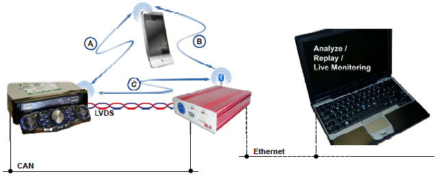
In the following we will take the connection between a mobile phone and an automotive head unit as an example for a typical connection of two consumer devices with significantly different development- and life-cycles and high expectations on the customer side. Figure 1 shows a typical setup of a automated Bluetooth testing scenario, based on the MLE 1000 Series Rapid Prototyping System.

Automated testing has many advantages: Tests can be more reproducible. Automated testing can eliminate false positives unlike manual testing. To achieve a high coverage of automated tests it helps to have a large set of simulation models for mobile phones as it is not sufficient to only test for conformance to standards like Hands Free Protocol or A2DP.
The MLE 1000 Series Rapid Prototyping System offers the full power of a Linux based workstation combined with a large variety of common interfaces. These interfaces can seamlessly be integrated into the automated testing process. With full control over both hard- and software, the creation of Bluetooth packet dumps and timestamping can be done at any level, from user interface down to communication between the controller and the interface phy. Tests can be programmed in high level programming languages like C or C++ , or even scripted in python, perl or bash. The Linux ecosystem around the testing program provides a lot more: For example test data can be sent via ethernet or saved on large external storage disks connected to USB.
Using the CAN interfaces it is quite simple to automatically control the head unit under test. With LVDS interfaces of the MLE 1000 Series Rapid Prototyping System it is even possible to capture the contents of the head unit’s displays (refer to MLE Technical Brief 20100129 – [MLETB]).
In the following, we will give a short overview over Bluetooth and two example scenarios employing the MLE 1000 Series Rapid Prototyping System and afterwards have a detailed look at a recorded handsfree protocol session.
Bluetooth is a wireless communication standard, which is standardized as IEEE 802.15.1. It utilizes the free 2.4 Ghz Industrial, Scientific and Medical (ISM) band with a fast frequency hopping technique to prevent the communication from being “jammed” by other devices in this band. Bluetooth devices are categorized into different classes according to their communication range. Class 1 devices can communicate over 100 meters, whereas class 2 and class 3 devices are for short distances of 10 and 1 meters respectively. The achievable theoretical data rates range between 24 MBit/s in Version 3.0 + HS (High Speed) down to 1 MBit/s and 3 MBit/s in Version 1.2 and Version 2.0 + EDR (Enhanced Data Rate).
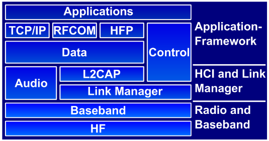
With its aim to replace a large set of different cables by wireless connectivity, the Bluetooth standard not only defines the radio and baseband level, but also the interface to the baseband controller and link manager, the so called Host Controller Interface (HCI). For easy replacement of cable based connections the Bluetooth standards also comprise a large set of protocols on top of the data layer that (from an application programmer’s point of view) provide the interface known from the wired connection, e.g. BNEP (Bluetooth Network Encapsulation Protocol) offers encapsulation of ethernet over the Bluetooth layer, so technically any program that already utilizes Ethernet can be routed over a bluetooth connection without changes in the software, as long as the connection is established by a controlling application and the bandwidth and latency of Bluetooth is sufficient. Apart from those standard communication links there is also a number of protocols that are specific to Bluetooth, e.g. the Hands Free Protocol (HFP). The multiple layers in the Bluetooth framework can be visualized as in Figure 3. To give a short overview over the variety of protocols belonging to Bluetooth Table 1 at the end of this document gives an excerpt of the most common protocols.

A quick research shows that the most commonly used Bluetooth chipsets for mobile phone and head unit applications are those from Broadcom, Cambridge Silicon Radio, Texas Instruments and Philips. Nevertheless, there is a significant number of other vendors available, most of which are mentioned in [PALO]. The MLE 1000 Series Rapid Prototyping System currently is equipped with a Bluetooth USB stick that uses the Cambridge Silicon Radio BlueCore 4 chipset. These chipsets can easily be identified via their USB ID 0a12:0001. Our engineering team uses these chipsets because they are widely available — even typical smartphones like the Apple iPhone 3G use them — and we experienced least problems with these chips. Of course, the Missing Link Electronics system also supports a large variety of other Bluetooth chips out of the box, in case the chipset matters. That is because the MLE 1000 Series Rapid Prototyping System utilizes the BlueZ Bluetooth stack on top of the Linux kernel.
Bluetooth is a standard for interlinking two usually different partners: One being a master and the other being a slave. Thus for testing purposes there are two significantly different test setups. One in which the tester simulates being the slave device and one where the tester simulates being the master device. The first setup utilizes the MLE 1000 Series Rapid Prototyping System as a slave to a mobile phone master and mimics a generic hands free unit according to the hands free specification. All reactions of the mobile phone to the stimuli are recorded for later playback in head unit testing. As seen in scenario (B) of Figure 2, the MLE 1000 Series Rapid Prototyping System behaves equivalent to a head unit as in scenario B from the automated testing system. Based on the OpenSource project nohands [SFNH] the hands free deamon can log the entire communication between the mobile phone and the simulated head unit at protocol-level. Via the hcidump utility there is also a dump on HCI level available.
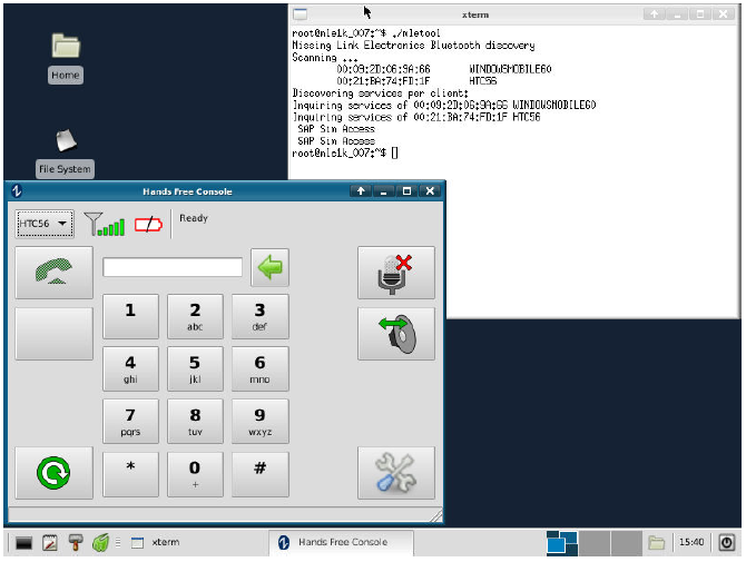
Figure 4 shows a screenshot of a MLE 1000 Series Rapid Prototyping System running hfconsole from the nohands project for connecting to a mobile phone via HFP1.5. In the background you can see the results from a simple Bluetooth discovery utility.

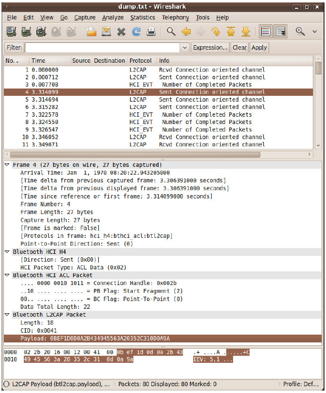
In the second setup a MLE 1000 Series Rapid Prototyping System mimics a generic mobile phone operating as a Bluetooth master and connects to an automotive head unit as shown in scenario (C) of Figure 2. This is possible because the MLE 1000 Series Rapid Prototyping System can also simulate being a mobile phone and thus can, for example, connect to automotive head units. With information previously recorded from scenario B it is also possible to simulate certain behavior patterns of certain mobile phones. Some head units use the AT+CGMI and the AT+CGMM commands, which request the manufacturer and model, to identify which phone is about to connect. At the moment typical head units do not initiate pairing, although this case can easily be added to the current setup. Apart from protocol-level based dumps the whole communication can be recorded on HCI level to storage devices attached to the MLE 1000 Series Rapid Prototyping System or transmitted in realtime via IP based services to a workstation. As shown in Figure 5 those dumps can then be further analyzed on any workstation running the powerful network protocol analyzing tool wireshark [WIRE].

Furthermore the MLE 1000 Series Rapid Prototyping System is able to record the signal strength of the Bluetooth connection, which may be useful in finding and analyzing problems. Apart from such connection specific information MLE 1000 Series Rapid Prototyping System also enables easy discovery of visible Bluetooth devices and service discovery protocol-level based verification of announced services. For debugging purposes the manufacturer ID of visible Bluetooth devices can also be read and logged.
Listing 1: BRSF-Command as Example of AT-Command class
Listing 1:
class BrsfCommand : public AtCommand {
        int          m_brsf;

public:
        BrsfCommand(HfpSession *sessp, int caps)
                : AtCommand(sessp), m_brsf(0) {
                char tmpbuf[32];
                sprintf(tmpbuf, "AT+BRSF=%d", caps);
                SetText(tmpbuf);
        }

        bool Response(const char *buf) {
                if (!strncmp(buf, "+BRSF:", 6)) {
                        int pos = 6;
                        while (IsWS(buf[pos])) { pos++; }

                        /* Save the output */
                        m_brsf = strtol(&buf[pos], NULL, 0);
                }
                return false;
        }

        bool OK(void) {
                GetSession()->SetSupportedFeatures(m_brsf);
                if (GetSession()->FeatureThreeWayCalling()) {
                        (void) GetSession()->AddCommand(
                                new ChldTCommand(GetSession()), false, 0);
                }
                return AtCommand::OK();
        }
        void ERROR(void) {
                /*
                 * Supported features can also come from the
                 * SDP record of the device, and if we initiated
                 * the connection, we should have them.  If not,
                 * we could get them, but we don’t, at least not yet.
                 */
                AtCommand::ERROR();
        }
};
In the following we will show implementation details of the hands free kit part. Afterwards we will show an excerpt of a log taken from a communication between two MLE 1000 Series Rapid Prototyping System. The log shows the handshake on service level between a hands free kit and an audio gateway. Due to readability this paper will refer to the hands free kit as a head unit and to the audio gateway as a mobile phone.
Listing 2: Handshake implementation for HFP1.5
Listing 2:
bool HfpSession::
HfpHandshake(ErrorInfo *error)
{
        assert(m_conn_state == BTS_Handshaking);

        /* This gets cleaned up by RfcommSession */
        assert(m_rfcomm_not == 0);
        m_rfcomm_not = GetDi()->NewSocket(m_rfcomm_sock, false);
        m_rfcomm_not->Register(this, &HfpSession::HfpDataReady);

        if (!AddCommand(new BrsfCommand(this, GetService()->m_brsf_my_caps),
                        false, error) ||
            !AddCommand(new CindTCommand(this), false, error) ||
            !AddCommand(new CmerCommand(this), false, error) ||
            !AddCommand(new ClipCommand(this), false, error) ||
            !AddCommand(new CcwaCommand(this), false, error))
                return false;

        return true;
}
Missing Link Electronics utilizes the nohands OpenSource project because of its flexible object oriented approach. This approach allows simple extensions to existing code without the risk of breaking functionality. Listings 1 and 2 show C++ source code taken from libhfp/hfp.cpp. Listing 1 shows an extension to the class of AT commands taking the AT+BRFS command, which is used for requesting supported features, as an example. The AtCommand::Response method allows running checks on the answer received after the command has been issued. An example of how to issue such commands can be seen in Listing 2, which shows the implementation of a handshake according to the hands free protocol. All commands which are to be issued are added to a FIFO using the AddCommand function and thus provide a very flexible interface in terms of adapting sequences of commands to different pre-recorded situations.
To give an example what is possible we will have a detailed look on a communication between to MLE 1000 Series Rapid Prototyping System. One MLE 1000 Series Rapid Prototyping System mimics a mobile phone and the other one mimics a Hands Free Kit. The MLE 1000 Series Rapid Prototyping System emulates a Hands Free Kit is used for logging the communication. The log is presented on the left column and the right column is used for short explanations of the log. The log shows the initialization sequence according to the Hands Free Protocol v1.5. The sequence of commands recorded equals the sequence of commands sent by the source code from Listing 2.
HFP_LOG_DAEMON: HCI Command status:
    0x00 0x01 0x0405
HFP_LOG_DAEMON: HCI Command status:
    0x00 0x01 0x041b
HFP_LOG_DAEMON: HCI Command status:
    0x00 0x01 0x0419
HFP_LOG_DAEMON: HCI Name request complete (0):
    "00:09:DD:60:FE:D6" -> "MLE1k2-007"
The MLE 1000 Series Rapid Prototyping System will not only log on protocol-level, but also on HCI level. Thus low level connection setup parts are also logged, as seen on the left the Bluetooth name of the handset is requested.
In the following we will see a typical communication according to the HFP1.5 protocol standard. All outgoing data is visualized using << and all incoming data is visualized using >>.
The service level connection initialization procedure is a predefined sequence of commands to negotiate capabilities and settings. According to the standard, first in the initialization the hands free kit (head unit) shall send the AT+BRSF=<head unit supported features> command to the mobile phone (Audio Gateway) to both notify the mobile phone of the supported features in the head unit, as well as to retrieve the supported features in the mobile phone using the +BRSF result code.
HFP_LOG_DAEMON: << AT+BRSF=63
The head unit sends its supported features.
HFP_LOG_DAEMON: >> +BRSF: 352
The mobile phone answers with its supported features. So the intersection between those two supported feature sets can be used for further communication.
HFP_LOG_DAEMON: >> OK
Any command the mobile phone receives has to be acknowledged. This is done via OK whenever the mobile phone knows the command and has processed the command correctly. In case of an unknown command or in the event of an error the mobile phone shall answer with ERROR.
HFP_LOG_DAEMON: << AT+CIND=?
This query from the head unit to the mobile phone is a read request. The read request can be identified by the =? token. The AT+CIND=? command is used for querying a list of indicators supported by the mobile phone. A good example for an indicator is field strength of the mobile signal or the battery charge level. This is information that is typically displayed on the display of the head unit.
HFP_LOG_DAEMON: >> +CIND: ("battchg",(0-5)),
    ("signal",(0-5)),("service",(0,1)),
    ("call",(0,1)),("callsetup",(0-3)),
    ("callheld",(0-2)),("roam",(0,1))
HFP_LOG_DAEMON: >> OK
The mobile phone answers with a list of its supported indicators. Each entry in the list consists of an identification string and the range of allowed values for the indicator. However, indicators are not identified by their identification string, but by the index in this list. So the battchg indicator, which holds the battery charge level, later on will be refered by “1”, the signal indicator (for signal strength) by “2” and so on.
HFP_LOG_DAEMON: << AT+CMER=3,0,0,1
HFP_LOG_DAEMON: >> OK
The AT+CMER= command (Mobile Termination Event Reporting) is used for setting the behavior of the mobile phone when an event occurs. In this case the head unit requests to be directly notified (3) only on indicator changes (,0,0,1). From now on the mobile phone shall send a +CIEV notification whenever an indicator changes.
HFP_LOG_DAEMON: << AT+CLIP=1
HFP_LOG_DAEMON: >> OK
The AT+CLIP= command (Calling Line Identification Presentation) is used for setting the behavior of the mobile phone in the event of an incoming call. In this case the head unit reports to the mobile phone that the head unit is capable of displaying phone numbers and would like to be given these phone numbers on incoming calls. From now on after a call is received and signaled via the +RING notification, the mobile phone shall send a +CLIP notification to the head unit with information about the caller.
HFP_LOG_DAEMON: << AT+CCWA=1
HFP_LOG_DAEMON: >> OK
The AT+CCWA= command (Call Waiting) is used for setting whether a mobile phone shall notify the head unit on incoming calls or not. In this case the head unit requests to be notified in the event of an incoming call. From now on the mobile phone shall send a +RING notification to the head unit in the event of an incoming call.
HFP_LOG_DAEMON: << AT+CIND?
Apart from the AT+CIND=? command described above, the AT+CIND? command is used for actively requesting the values of the indicators. This is done as a last step in the initialization process, so that the headunit has defined and correct values for the indicators.
HFP_LOG_DAEMON: >> +CIND: 5,5,1,0,0,0,0
HFP_LOG_DAEMON: >> OK
The mobile phone responds to the query of indicators. The response is a comma separated list with the values of the indicators. The ordering of the indicators is same as returned to the AT+CIND=? command above. So for interpreting the values saving the assignment between index and indicator is important.
We have shown that the MLE 1000 Series Rapid Prototyping System provides an easy way to analyze a HFP communication. With the powerful Linux architecture in the background these logs can easily be saved, searched and put into scripts both for replay and interactive reactions using other interfaces like the CAN-Interface. Userspace tools like cansend and candump can be used to control an automotive head unit for automated testing. With the flexible FPGA architecture it is even possible to automatically control a cellphone by connecting the FPGA to the phone, instead of its keypad. Moreover, the LVDS capabilities of the MLE 1000 Series Rapid Prototyping System can even make it possible to capture the contents of a head unit’s display and with the whole Linux ecosystem around even simple OCR may be possible, e.g. for verification of contacts displayed by the head unit transmitted via OBEX/PBAP.
| Protocol | Description | MLE supported |
|---|---|---|
| LMP (Link Management Protocol) | Controls radio link between two devices | yes |
| L2CAP (Logical Link Control & Adaption Protocol) | Multiplexing multiple protocol layer connections between two devices | yes |
| SDP (Service Discovery Protocol) | Discovers services provided by devices known or visible | yes |
| HCI (Host/Controller Interface) | standardized communication between controller and host stack | yes |
| RFCOMM (Radio Frequency COMMunications) | cable replacement protocol for a virtual serial data stream, emulating RS-232 | yes |
| BNEP (Bluetooth Network Encapsulation Protocol | Encapsulate 802.3 (Ethernet) for use with Bluetooth | yes |
| AVCTP (Audio/Visual Control Transport Protocol) | Transfer remote control buttons over L2CAP channels | yes |
| AVDTP (Audio/Visual Data Transport Protocol) | Foundation for A2DP high quality audio transfers | yes |
| OBEX (OBject EXchange) | Exchanging Objects, similar to IrDA OBEX | partly |
| A2DP (Advanced Audio Distribution Profile) | High quality audio streaming between capable devices | yes |
| HFP (Hands Free Profile) | Profile for connecting a head unit and a mobile phone and controlling the mobile phone | yes |
| HSP (Headset Profile) | Most commonly used profile for connecting a headset to a mobile phone | yes |
| PAN (Personal Area Networking) | Networking over Bluetooth (e.g. used for Internet connection sharing of mobile phones) | yes |
| PBAP (Phone Book Access Profile) | Access to the mobile phone’s phonebook based on OBEX | client |
| SIM Access Profile (SAP, SIM, rSAP) | Allows direct access to SIM cards in mobile phones | preliminary |
| DUN (DialUp Networking) | Uses AT modem command set for dialing | preliminary |
References
[PALO] Palo Pacific Technology, Pty Ltd:
Palowireless Wireless Resource Center, retrieved January 2010.
http://www.palowireless.com/database/btchipsets.asp
[HFP1.5] Bluetooth Special Interest Group (SIG):
HANDS-FREE PROFILE 1.5, November 2005.
http://www.bluetooth.com/NR/rdonlyres/C0F90A55-BDE4-4FB3-A4FF-DAB0F137DBDF/1762/HFP15_SPEC_V10r00.pdf
[SFNH] Sourceforge.net:
nohands: HFP for Linux.
http://nohands.sourceforge.net
[WIRE] Wireshark.org:
Wireshark – the world’s foremost network protocol analyzer.
http://www.wireshark.org
[MLETB] Missing Link Electronics:
TB 20100129: Deep Image Analysis for Multimedia Systems, 2010.
https://devzone.missinglinkelectronics.com/wp-content/uploads/2023/07/MLE-TB20100129.pdf
🌐 www.missinglinkelectronics.com
MLE (Missing Link Electronics) is offering technologies and solutions for Domain-Specific Architectures, which focus on heterogeneous computing using FPGAs. MLE is headquartered in Silicon Valley with offices in Neu-Ulm and Berlin, Germany.
