XPS USB Host Controller Developer’s Guide
This MLE Technical Brief is intended for embedded systems and FPGA designers who seek to integrate the XPS_USB_HOST Controller IP Core. Originally developed and shipped by Xilinx, Inc. MLE has been marketing and supporting this IP core for Xilinx customers, since October 2011. This Technical Brief gives you an introduction into the functionality of USB 2.0 in general, describes the usage in a FPGA design and provides references to further documentation.
Foundation of this Technical Brief is the XPS_USB_Host Controller Linux Reference Design from MLE. Using this reference design the various modes of USB can be evaluated based on some basic and easy to reproduce test-cases. This highlights how the
XPS_USB_HOST Controller IP Core operates in conjunction with Linux running on an embedded CPU (Xilinx MicroBlaze or PowerPC) inside a Xilinx FPGA device.
Copyright © 2026 Missing Link Electronics. All rights reserved. Missing Link Electronics, the stylized Missing Link Electronics MLE logo are the service mark and/or trademark of Missing Link Electronics, Inc. All other product or service names and trademarks are the property of their respective owners.
1 USB Backgrounder
Universal Serial Bus (USB) is an industry standard developed in the mid-1990s. Used cables, connectors and communication protocols for connection, communication and power supply between computers and electronic devices are defined therein.
1.1 Speed Modes of USB
USB 2.0 declares the speed modes low-speed, full-speed and high-speed. Not every USB 2.0 device must support all three speed modes. The XPS_USB_HOST Controller IP Core only supports full-speed and high-speed modes.
1.2 Bus Topology of USB
The USB physical interconnect is a tiered star topology. A hub is at the center of each star and the wire segments are point-to-point connections.
There is only one USB host in a USB hierarchy. The USB interface to the host computer system is referred to as host controller. This host controller may be implemented in a combination of hardware, firmware, or software. A root hub is integrated within the host system to provide one or more attachment points.
USB devices are either hubs, which provide additional attachment points to the USB or functions, which provide capabilities to the system, such as e.g. keyboards, web-cams, storage devices, or speakers.
USB On-The-Go (OTG) allows USB devices to act as USB host. This enables the device to switch operation between host and device.
The XPS_USB_HOST Controller IP Core can only act as a USB host.
1.3 Transfer Types of USB
USB supports functional data and control exchange between the USB host and a USB device as a set of either uni-directional or bi-directional pipes. USB data transfers take place between host software and a particular endpoint on a USB device. In general, data movement though one pipe is functionally independent from the data flow in other pipes.
The USB architecture comprises four basic types of data transfers:
Control-Transfer:
Control data is used by the USB system software to configure devices when they are first attached. Other driver software can choose to use control transfers in implementation specific ways. Data delivery is loss-less.
Bulk-Transfer:
Bulk data typically consists of larger amounts of data, for example used for printers or scanners. Bulk data is sequential. Reliable exchange of data is ensured at the hardware level by using error detection in hardware and invoking a limited number of retries in hardware. Also, the bandwidth taken up by bulk data can vary, depending on other bus activities.
Interrupt-Transfer:
A limited-latency transfer to or from a device is referred to as interrupt data. Such data may be presented for transfer by a device at any time and is delivered by the USB at a rate no slower than specified by the device. Interrupt data typically consists of event notification, characters, or coordinates that are organized as one or more bytes. Unlike the name suggests, a USB device does not trigger CPU interrupts. The USB host has to poll devices for new information.
Isochronous-Transfer:
Isochronous data is continuous and real-time in creation, delivery, and consumption. Timing-related information is implied by the steady rate at which isochronous data is received and transferred. Isochronous data must be delivered at the rate received to maintain its timing. A typical example of isochronous data is voice. The timely delivery of isochronous data is ensured at the expense of potential transient losses in the data stream. In other words, any error in electrical transmission is not corrected by hardware mechanisms such as retries.
The XPS_USB_HOST Controller IP Core supports all transfer types of the USB 2.0 standard listed above.
1.4 USB Hot Plug
USB 2.0 is hot pluggable by specification. This means that a USB device can be plugged to a running system. The XPS_USB_HOST Controller IP Core is ready for hot plugging.
1.5 Further Documentation
The information in this chapter is derived from USB 2.0 specification [1]. For further information please see the following documentations:
- USB 2.0 specification [1]
- MLE website for the XPS_USB_HOST Controller IP Core [2]
- Xilinx data-sheet for the XPS_USB_HOST Controller IP Core [3]
- Xilinx Wiki – USB Host System Setup [4]
- Xilinx Wiki – USB Host Controller Driver [5]
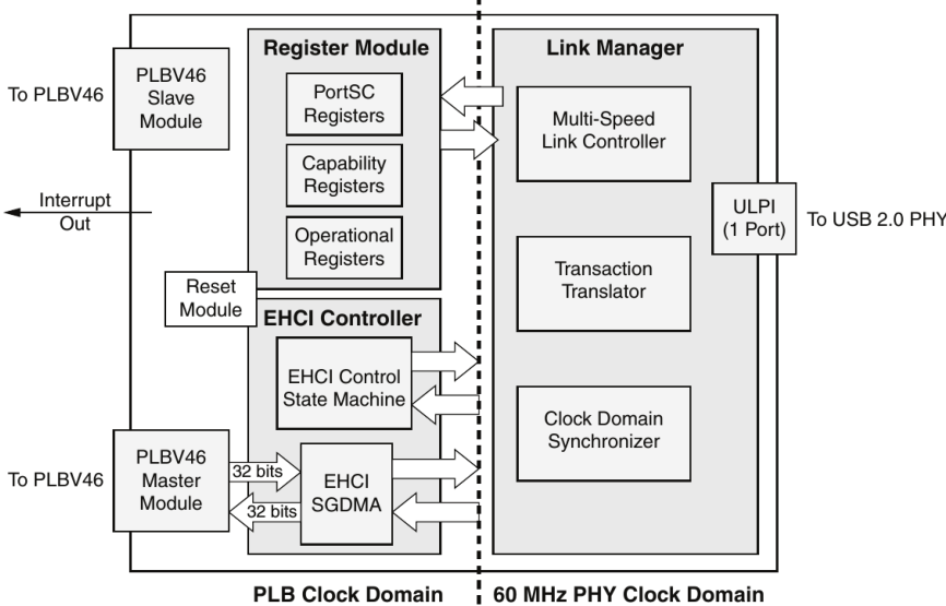
2 The XPS_USB_HOST Controller IP Core
The XPS_USB_HOST Controller IP Core is designed to act as controller of a USB host PHY. USB On-the-Go is not supported. Further a ULPI USB PHY is required to act with the IP core. Such a PHY can be e.g. a MLE-PHY or a USB3300 USB HS Board from Waveshare [6].
2.1 Supported Features
The XPS_USB_HOST Controller IP Core:
- supports full-speed and high-speed modes,
- is a USB host (and only a host),
- supports all transfer types of USB 2.0,
- supports hot plugging,
- is EHCI compliant and, thereby, supported by Linux.
2.2 Supported Speed Modes
By default the XPS_USB_HOST Controller IP Core supports only the high-speed mode. As an option the full-speed mode can also be enabled, this must be done prior to FPGA synthesis. Figure 2 shows the XPS Core Config of the XPS_USB_HOST Controller IP Core with enabled full-speed Support and Listing 1 shows the corresponding line in the MHS-file (change the parameter to 0 to disable Full-speed mode). The low-speed mode is not supported at all.
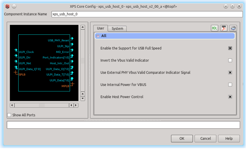
Listing 1: parameter for enabled full-speed mode in mhs-file
PARAMETER C_SUPPORT_USB_FS = 1
2.3 Revisions and Deliverables
There are different varieties of the XPS_USB_HOST Controller IP Core available. How they can be purchased and what has to be considered because of their licensing is shown in Table 1.
Originally shipped with Xilinx ISE are so-called Evaluation Cores which comprise a timebomb. This time-bomb will trigger after approximately eight hours, effectively disabling the operation of the XPS_USB_HOST Controller IP Core. Please contact MLE [7] to get a fully licensed IP Core without any time-bombs. You will receive two packages: (1) pcore for EDK and (2) FLEXlm license key file.
| IP Version | Delivery | License |
|---|---|---|
| 1.00.a | Xilinx ISE 11.x | evaluation only |
| 1.01.a | Xilinx ISE 11.x & 12.x | evaluation only |
| 1.02.a | MLE | compile-time license |
| 2.00.a | MLE | compile-time license |
The XPS_USB_HOST Controller IP Core can be used like any other pcore: Unpack both packages into your design project. The corresponding core directory, e.g. “xps_usb_host_v2_00_a”, has to be copied into the pcore directory of the design project. If the XPS GUI is already open, it is required to rescan the user repositories. To install the FLEXlm license key file please read the Xilinx user guide UG798 [8] or follow the instructions shipped with the license key file.
2.4 License Management
To build a design with the XPS_USB_HOST Controller IP Core a license key is required. The different licenses are described above and the following will describe the handling of licenses and cores from MLE.
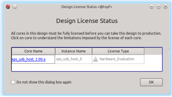
In the GUI of XPS it is possible to check the Design License Status under the Hardware section. Because it is a compile-time license key this window looks like Figure 3. This window is also shown at the end of every build process (in GUI mode) of a design instantiating this core.
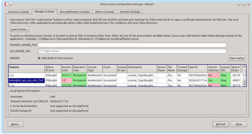
To check the license status of the XPS_USB_HOST Controller IP Core start the Xilinx License Configuration Manager. If the licensing is okay, the entry ipmsnglnk_xps_usb_ehci_full will be displayed as shown in Figure 4 with green highlighted entries for the correct Host id and License CRC. For more information on licensing please see the Xilinx User Guide
UG798 [8].
After a successful build of a design instantiating the XPS_USB_HOST Controller IP Core the message of Listing 2 can be found in the log file. Please note that the license is (erroneously) called Hardware Evaluation even though a proper license key has been installed.
Listing 2: Message in log file after build with valid license key
INFO : coreutil - Hardware Evaluation license for component < xps_usb_host > found. The generated design
       will cease to function in the programmed device after operating for some period of time. This allows
       you to evaluate the component in hardware. You are encouraged to license this component.
For ordering information , please refer to the product page for this component on : www.xilinx.com
Without a valid license key the build will stop with an error case, printing one of the following error messages on the console. Listing 3 shows the error that occurs while building a design with a wrong host ID in the license key. Listings 4 and 5 show the error output on console and in the called output file when building a design with the XPS_USB_HOST Controller IP Core without any license key for this core.
Listing 3: Error message while building a design with the XPS_USB_HOST Controller IP Core with
a wrong host ID in the license key file
ERROR : EDK - INFO : Security :67 - XILINXD_LICENSE_FILE is set to
        ’/ home / share / old - opt /xilinx121 / ISE_DS / EDK / data /
        core_licenses :/ home / fass / user /. Xilinx :/ home / fass / user
        /. mlew / xilinx / license . all ’ in / home / fass / user /.
        flexlmrc .
        INFO : Security :68 - Please run the Xilinx License Configuration
        Manager
               ( xlcm or " Manage Xilinx Licenses ")
               to assist in obtaining a license.
        ERROR : Security :14 - No feature was available for ’XPS ’.

        Invalid host .
            The hostid of this system does not match the hostid
            specified in the license file .
        Feature : XPS
        Hostid : 902 b3431171e
        License path :
        (...)
Listing 4: Error message on console while building a design with the XPS_USB_HOST Controller IP Core without license key
INFO : EDK - The following instances are synthesized with XST . The MPD
     option IMP_NETLIST = TRUE indicates that a NGC file is to be produced
     using XST 3 synthesis . IMP_NETLIST = FALSE ( default ) instances are
     not synthesized .
INSTANCE : xps_usb_host_1 -
/ home / fass / user / workspace / usb_core_testing / ML_noLic_unencripted_mle507 / system. mhs line 378 - Running XST synthesis
ERROR : Xst :1484 - A core is unlicensed !
ERROR : EDK - Aborting XST flow execution !
INFO : EDK - Refer to
      / home / fass / user / workspace / usb_core_testing /
      ML_noLic_unencripted_mle507 / synthesis / xps_usb_host_1_wrapper_xst .
      srp for details

Running NGCBUILD …

Rebuilding cache …
ERROR : EDK - platgen failed with errors !
make : *** [ implementation / xps_usb_host_1_wrapper . ngc ] Error 2
Listing 5: Error message in log file “‘xps_usb_host_1_wrapper_xst.srp”’, mentioned on console
Analyzing hierarchy for entity < xps_usb_host_1_wrapper > in library < work >
     (architecture <STRUCTURE >) .
INFO : coreutil - No license for component < ipmsnglnk_xps_usb_ehci_full > found . You
     may use the customization GUI for this component but you will not be able to
     generate any implementation or simulation files .

      For license installation help , please visit :
      www . xilinx . com / ipcenter / ip_license / ip_licensing_help . htm

      For ordering information, please refer to the product page for this component on:
     www . xilinx . com FLEXlm Error : No such feature exists . ( -5 ,21)
ERROR : Xst :1484 - A core is unlicensed !
2.5 Timing Closure
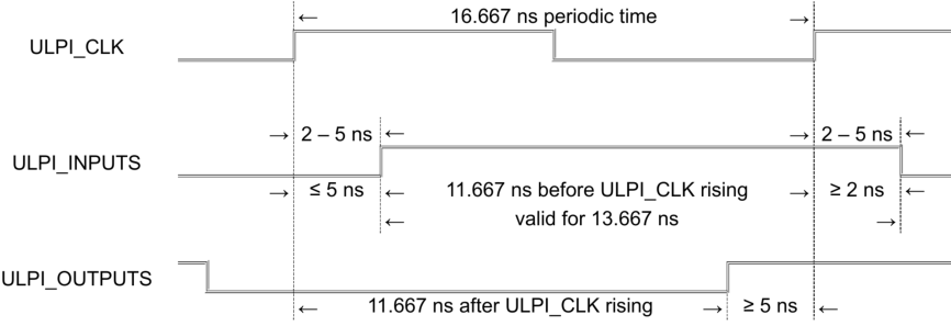
To ensure a proper timing of the signals between XPS_USB_HOST Controller IP Core and USB PHY it is necessary to set constraints as described below. This constraints can be found in the provided UCF-file. Figure 5 shows the timing of the ULPI signals with the delay times of the USB3300 PHY as declared in the data sheet [9].
PLB-Clock:
In the design example the PLB_CLK runs with 100 MHz (clock period = 10 ns) and 50 % duty cycle. Master and slave PLB of the XPS_USB_HOST Controller IP Core must run at the same clock. The constraint to this clock is shown in Listing 6.
Listing 6: PLB-clock constraints
# Set the PLB_CLK constraints
NET " PLB_CLK " TNM_NET = " PLB_CLK ";
TIMESPEC " TS_PLB_CLK " = PERIOD " PLB_CLK " 10 ns HIGH 50%;
ULPI-Clock:
The ULPI_CLK runs with 60 MHz (clock period = 16667 ps) and 50 % duty cycle. This is constrained in Listing 7.
Listing 7: ULPI-clock constraints
# Set the xps_usb_host_0_ULPI_Clock_pin constraints
Net " xps_usb_host_0_ULPI_Clock_pin " CLOCK_DEDICATED_ROUTE = FALSE ;
Net " xps_usb_host_0_ULPI_Clock_pin " TNM_NET = " xps_usb_host_0_ULPI_Clock_pin ";
TIMESPEC TS_xps_usb_host_0_ULPI_Clock_pin = PERIOD " xps_usb_host_0_ULPI_Clock_pin "
        16667 ps HIGH 50%;
Delay Offset of Dir-pin:
ULPI_Dir switches the direction of the data signals between input and output. The switching delay must be smaller than 5 ns, because of signal validity in the communication with the ULPI PHY. To have a safety gap of 0.5 ns we set the MAXDELAY to 4.5 ns, like constrained in Listing 8.
Listing 8: Delay offset of Dir-pin
# Set MAX DELAY constraint on ULPI_Dir pin
NET " xps_usb_host_0 / ULPI_Dir " MAXDELAY =4.5 ns ;
Clock Domain Crossing between PLB and ULPI:
To constrain the clock domain crossing between the PLB and ULPI domains the code of Listing 9 is required.
Listing 9: Clock domain crossing between PLB and ULPI
# Cross clock domain timing Constraints between ULPI_Clk and SPLB_Clk
# DMA is included and both slave and master plb clock frequencies are EQUAL
NET " xps_usb_host_0 / ULPI_Clock " TNM_NET = " ulpi_0_clock_net ";
NET " mb_plb / PLB_Clk " TNM_NET = " splb_0_clock_net ";
TIMEGRP " ulpi_0_clock_grp " = " ulpi_0_clock_net ";
TIMEGRP " splb_0_clock_grp " = " splb_0_clock_net ";
TIMESPEC TS_splb_0_to_ulpi_0_clk = FROM " splb_0_clock_grp " TO " ulpi_0_clock_grp " 32.2ns DATAPATHONLY ;
         # (2 * ULPI Clock period - 1)
TIMESPEC TS_ulpi_0_to_splb_0_clk = FROM " ulpi_0_clock_grp " TO " splb_0_clock_grp " 19.0ns DATAPATHONLY ;
         #(2 * PLB Clock period âĂŞ 1)
ULPI-inputs:
The ULPI_Inputs are constrained with the code of Listing 10 and explained below.
Listing 10: ULPI-inputs constraints
NET " xps_usb_host_0_ULPI_Data_pin <0 >" TNM = ULPI_INPUTS ;
NET " xps_usb_host_0_ULPI_Data_pin <1 >" TNM = ULPI_INPUTS ;
NET " xps_usb_host_0_ULPI_Data_pin <2 >" TNM = ULPI_INPUTS ;
NET " xps_usb_host_0_ULPI_Data_pin <3 >" TNM = ULPI_INPUTS ;
NET " xps_usb_host_0_ULPI_Data_pin <4 >" TNM = ULPI_INPUTS ;
NET " xps_usb_host_0_ULPI_Data_pin <5 >" TNM = ULPI_INPUTS ;
NET " xps_usb_host_0_ULPI_Data_pin <6 >" TNM = ULPI_INPUTS ;
NET " xps_usb_host_0_ULPI_Data_pin <7 >" TNM = ULPI_INPUTS ;
NET " xps_usb_host_0_ULPI_Dir_pin " TNM = ULPI_INPUTS ;
NET " xps_usb_host_0_ULPI_Nxt_pin " TNM = ULPI_INPUTS ;
TIMEGRP " ULPI_INPUTS " OFFSET = IN 11.667 ns VALID 13.667 ns BEFORE " xps_usb_host_0_ULPI_Clock_pin "
          RISING ;
The ULPI_INPUTS are output signals of the USB-PHY and they show delays relating to the ULPI_CLK. In the case of a USB3300-PHY this delay amounts between 2 ns and 5 ns. This means ULPI_INPUTS signals are valid from 2 ns to 5 ns after each rising edge of ULPI_CLK. This values have to be subtracted from clock period of the ULPI_CLK:
16.667 ns – 5 ns = 11.667 ns
16.667 ns – ( 5 ns – 2 ns ) = 13.667 ns
So the ULPI_INPUTS signals are valid from 11.667 ns ns to 13.667 ns ns before each rising
edge of ULPI_CLK, like set in line 11 of Listing 10.
ULPI-outputs:
The ULPI_OUTPUTS are constrained with the code of Listing 11 and explained below.
Listing 11: ULPI-outputs constraints
NET " xps_usb_host_0_ULPI_Data_pin <7 >" TNM = ULPI_OUTPUTS ;
NET " xps_usb_host_0_ULPI_Data_pin <6 >" TNM = ULPI_OUTPUTS ;
NET " xps_usb_host_0_ULPI_Data_pin <5 >" TNM = ULPI_OUTPUTS ;
NET " xps_usb_host_0_ULPI_Data_pin <4 >" TNM = ULPI_OUTPUTS ;
NET " xps_usb_host_0_ULPI_Data_pin <3 >" TNM = ULPI_OUTPUTS ;
NET " xps_usb_host_0_ULPI_Data_pin <2 >" TNM = ULPI_OUTPUTS ;
NET " xps_usb_host_0_ULPI_Data_pin <1 >" TNM = ULPI_OUTPUTS ;
NET " xps_usb_host_0_ULPI_Data_pin <0 >" TNM = ULPI_OUTPUTS ;
NET " xps_usb_host_0_ULPI_Stp_pin " TNM = ULPI_OUTPUTS ;
TIMEGRP " ULPI_OUTPUTS " OFFSET = OUT 11.667 ns AFTER " xps_usb_host_0_ULPI_Clock_pin " RISING ;
The ULPI_OUTPUTS are the input signals at the USB PHY and need to have a setup time before each rising edge of the ULPI_CLK. In the case of a USB3300 PHY this delay is 5 ns. This means ULPI_OUTPUTS signals have to be valid 5 ns before each rising edge of ULPI_CLK, which can be set as shown in Listing 12.
Listing 12: ULPI-outputs timing
TIMEGRP " ULPI_OUTPUTS " OFFSET = OUT 5 ns BEFORE " xps_usb_host_0_ULPI_Clock_pin " RISING ;
It is also possible to calculate the inverse. This means that ULPI_OUTPUTS signals are valid 16.667 ns – 5 ns = 11.667 ns after each rising edge of ULPI_CLK, like set in line 10 of Listing 11.
Issue:
It may happen, that the constraint for ULPI_Dir, as described in Listing 8, is not met during implementation of the XPS_USB_Host Controller Linux Reference Design. In this case the error message shown in Listing 13 will appear on the console.
Listing 13: Error on console when the timing of a design is not met
ERROR : 1 constraint not met .
PAR could not meet all timing constraints . A bitstream will not be generated .
The source of the timing problem can be found in the timing report under:
<design>/implementation/system.twr
If the error is as expected, a negative slack of ULPI_Dir can be found in the log file:
Listing 14: Negative slack of ULPI_Dir in the log file
Slack : -0.001 ns xps_usb_host_0 / xps_usb_host_0 / I_USBHC_LM / ulpi2mlc_ulpi_dir
Error : 4.501 ns delay exceeds 4.500 ns timing constraint by 0.001 ns
Explanation:
ULPI_Dir switches the direction of the data signals between input and output. The switching
delay must be smaller than 5 ns because of signal validity in the communication with the
ULPI PHY. To have a safety gap of 0.5 ns the MAXDELAY is set to 4.5 ns. This is constraint
in the ucf-file as shown in Listing 8. The problem is, that the constraint will not be met if we
use a MAXDELAY of 5 ns, too. In this case the tool limits the rooting effort and the slack on
this wire could be even worse, e.g. – 0.046 ns.
Workaround:
XPS doesn’t support manual optimization of a design, but it is possible to treat timing
failures not as errors. This can be set in the system.xmp with the instruction of Listing 15.
Listing 15: Instruction for XPS to treat timing failures not as errors
EnableParTimingError : 0
This command will be ignored when building the design on console, so it is required to use the GUI of XPS. The option EnableParTimingError can also be disabled under:
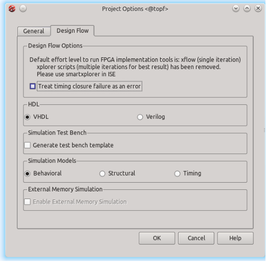
Project → Project Options → Design Flow
Remove the check mark for option “Treat timing closure failure as error” as shown in Figure 6. After that the bitstream can be generated via:
Hardware → Generate Bitstream
Attention:
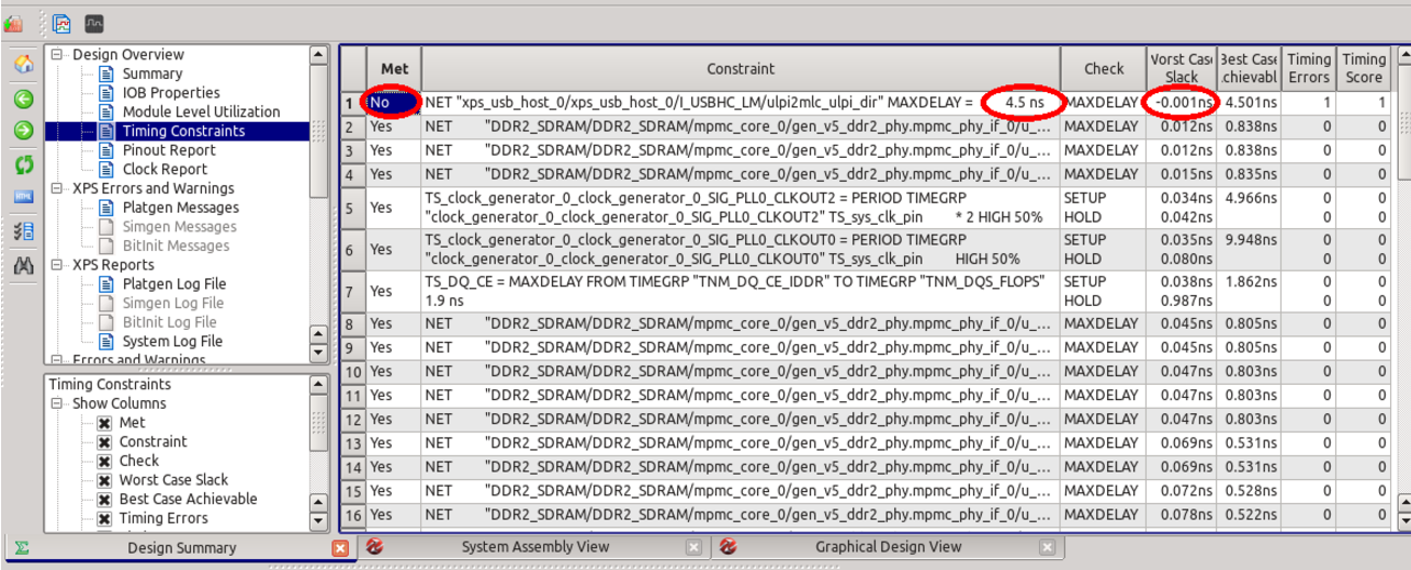
This workaround is potentially dangerous, as it may hide other timing violations that exist in the design. Please carefully review all newly calculated timings for the design once the bitstream has been generated. This can be easily done in the Design Summary under:
Design Overview → Timing Constraints
An example is shown in Figure 7. Check the column Met: Usually all entries should be stated as Yes. If there is an No analyze the Worst Case Slack in this line. If it is the said problem with the constraint for ULPI_Dir, this slack must be smaller than 0.5 ns! In the example of Figure 7 it is just -0.001 ns. Again, if there are other timing constraints not met, you must carefully analyze those timing violations!
3 The XPS_USB_Host Controller Linux Reference Design
To ease the integration of the XPS_USB_HOST Controller IP Core with Xilinx MicroBlaze running Linux, MLE has put together an integrated, pre-validated reference design. This reference design is based on the PLB architecture and uses a big-endian MicroBlaze implementation in a Virtex-5 FPGA. As a hardware platform for USB evaluation and testing MLE uses the Xilinx ML507 [10] development kit. The following describes the relevant setup for testing the XPS_USB_HOST Controller IP Core on the ML507. Feel free to use those settings as an example to make the XPS_USB_HOST Controller IP Core work on
your target hardware.
An AXI-based reference design integrating Linux with a little-endian MicroBlaze is in works.
Please contact us for more information.
3.1 Getting Started
This section gives a step by step instruction on how to build the ML507 MicroBlaze USB
design on a Linux workstation.
3.1.1 Hardware
Go to the hw directory and start a Xilinx EDK 14.7 environment. To build the DTS-file for
the design, type:
make system.dts
When the DTS-file is ready, it is located in the hw directory.
Subsequently start Xilinx Platform Studio (XPS) to implement the hardware, type:
xps
and open the project:
hw/system.xmp
Then disable treating errors by timing closure, click:
Project – Project Options – Design Flow
and untick the option as shown in Figure 6:
Treat timing closure failure as an error
Next start generation of the bitstream, click:
Hardware – Generate Bitstream
This will take about 30 minutes, depending on the running machine.
After the bitstream is generated, review the timing summary as shown in Figure 7. Click:
Design Overview – Timing Constraints
Check the Worst Case Slack in the line with the entry No in the column Met. It must be
smaller than 0.5ns! If the timing is okay, close XPS. The bitstream is can be found in:
hw/implementation/system.bit
3.1.2 Linux
This section gives a step by step instruction on how to build the Linux kernel for the ML507 MicroBlaze USB design. First you have to build the hardware-design and an DTS-File for the given design. These steps are described above.
Change to a Xilinx EDK 14.7 environment, then checkout the Linux kernel sources. MLE recommends to use the source code provided by Xilinx. The easiest way to do this is by cloning the GIT-Repository and checkout the Tag xilinx-v2014.3 by executing in the sw directory of the design example:
git clone https://github.com/Xilinx/linux-xlnx -b xilinx-v2014.3
Once this is done we must apply a little patch to be able to use the driver for the XPS_USB_HOST Controller IP Core. This patch only adds a missing include to the file drivers/usb/host/ehcixilinx-of.c. Just go into the linux-xlnx directory and execute:
cd linux-xlnx
git apply ../0001-ehci-xilinx-of.c-added-of_irq-include.patch
Next step is to apply the kernel-configuration. To use the provided config you can execute
the following commands:
cp ../ml507_mb_usb_kernel.config .config
make ARCH=microblaze oldconfig
You must also provide the DTS-File. For this, copy the created DTS-File (or the provided one) into the sub-folder arch/microblaze/boot/dts by executing:
cp ../ml507_mb_usb.dts arch/microblaze/boot/dts/ml507_mb_usb.dts
Now you are ready to build the Linux kernel by using the so-called method simpleImage. Here you have to provide the name of the DTS-File to use. For example:
make ARCH=microblaze CROSS_COMPILE=microblaze-xilinx-linux-gnu- simpleImage.ml507_mb_usb -j8
uses the DTS-File ml507_mb_usb.dts from arch/microblaze/boot/dts.
Once you have all the binaries needed you can create the ACE-file and copy it onto a CF-card. To create the ACE-file you need the bitfile and the kernel image. To get a correct ACEFile for big-endian (which is used for PLB architectures) you have to follow a workaround: Check the content of the file generate_ace.opt as in Listing 16:
Listing 16: Content of file generate_ace.opt
- jprog
- board ml507
- target mdm
- hw ../../ implementation / system . bit
- elf arch / microblaze / boot / simpleImage . ml507_mb_usb
- debugdevice devicenr 1 cpunr 1 cpu_version microblaze_v72
- ace ../ ml507_mb_usb_ace . ace
Here hw is the bitfile, elf is the kernel image and ace is the output-file. The debug device must be set to the microblaze_v72 to force creation of a big-endian ACE-File.
This file gives all the information to the script which creates the ACE-File. To run creation execute:
xmd -tcl $XILINX_EDK/data/xmd/genace.tcl -opt generate_ace.opt
For the RootFS we suggest the default configuration of Busybox version 1.22 which can be downloaded from the Xilinx Homepage [13]. For more information please refer to the Xilinx Wiki page [14].
3.1.3 CF-Card Boot Image
The final step is to prepare the CF-card for the ML507 board. To do this you need a CF-card and a card reader on your local pc. The CF-card has to be partitioned and formatted as follows:
Partition 1: 100MB FAT16
Partition 2: 500MB EXT3 (or rest of space left)
To partition the CF-card use fdisk. Execute (you have to be root):
fdisk /dev/sd <X>
In fdisk first delete all partitions if there are any by typing [d] and selecting the partition number, until the device is empty. Then create the first partition as primary partition by typing [n] [p] [1] [return] +100M [return]. Create the second partition by typing [n] [p] [2] [return] [return]. Type [p] and review the partitions. If it is okay write the new table by typing [w].
The next step is to create the file-systems. For this use mkfs by executing (with root rights):
mkfs.fat -F 16 /dev/sd1
mkfs.ext3 /dev/sd2
Now you can copy the files onto the CF-card. Copy all the data from the provided cf-card_bootpartition.tar.gz to the first partition. Replace the file ML50X/cfg0/v200.ace on the
first partition with the ACE-File created.
Copy all contents from the provided cf-card_rootfs.tar.gz to the second partition.
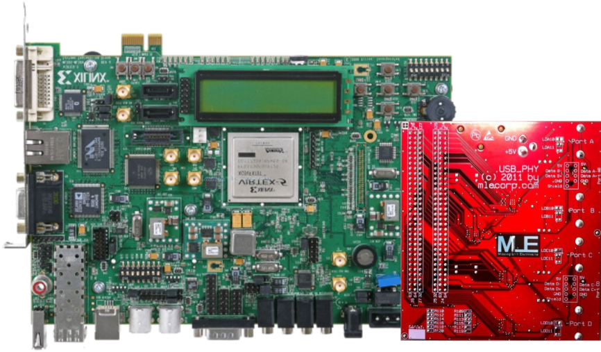
3.1.4 ML507 Board Settings
The ML507 board features a Virtex 5 XC5VFX70T FPGA device. Besides the ML507 board you will need an add-on board with an ULPI PHY compatible with the XPS_USB_HOST Controller IP Core. In our example we use an MLE-PHY board with four USB3300 phys and plug it to the ML507 board as shown in Figure 8.
Any pre-settings on the ML507 board have to be done before starting:
- User selectable I/O voltage: select 3,3V on J20 (next to the power jack).
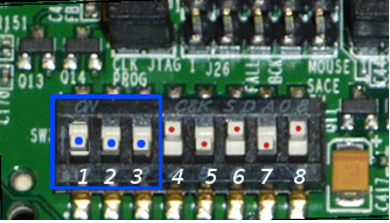
- Configuration address and mode DIP switches (SW3): 0 0 0 1 0 1 0 1 (Figure 9(a)).
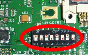
- Configuration of clocking options (SW6 on back plane): 1 0 1 0 1 0 1 0 (Figure 9(b)).
- Connect the power-supply to the board.
- Insert the prepared CF-card into the card-slot.
Please refer to the Xilinx User Guide [11] for more details of the board.
3.1.5 Starting Up
Once all settings are applied, connect the COM1 of the ML507 board to your workstation and open a terminal (for example, you can use minicom and connect to /dev/ttyUSB0 with the settings 115200 8N1). Then switch on the board via SW1. The Linux system will boot while printing boot messages into the terminal. The entire boot phase may take about 45 seconds, then the XPS_USB_Host Controller Linux Reference Design system is up and running.
3.2 About the Design
3.2.1 Design Components
The XPS_USB_Host Controller Linux Reference Design has been created using Xilinx EDK XPS 14.7. It is a standard Base System Builder (BSB) project with additional XPS_USB_HOST Controller IP Core. Table 2 lists the inserted components of the design example. Any further details are listed below.
| Component | Instance | HW_VER | BADSEADDR |
|---|---|---|---|
| microblaze | microblaze_0 | 8.50.c | 0x50000000 |
| plb_v46 | mb_plb | 1.05.a | |
| lmb_v10 | ilmb | 2.00.b | |
| lmb_v10 | dlmb | 2.00.b | |
| lmb_bram_if_cntlr | dlmb_cntlr | 3.10.c | 0x00000000 |
| lmb_bram_if_cntlr | ilmb_cntlr | 3.10.c | 0x00000000 |
| bram_block | lmb_bram | 1.00.a | |
| xps_uartlite | RS232_Uart_1 | 1.02.a | 0x84000000 |
| xps_ethernetlite | Ethernet_MAC | 4.00.a | 0x81000000 |
| mpmc | DDR2_SDRAM | 6.06.a | 0x50000000 |
| xps_sysace | SysACE_CompactFlash | 1.01.a | 0x83600000 |
| xps_timer | xps_timer_0 | 1.02.a | 0x83c00000 |
| clock_generator | clock_generator_0 | 4.03.a | |
| mdm | mdm_0 | 2.10.a | 0x84400000 |
| proc_sys_reset | proc_sys_reset_0 | 3.00.a | |
| xps_intc | xps_intc_0 | 2.01.a | 0x81800000 |
| plb_v46 | plb_v46_0 | 1.05.a | |
| xps_usb_host | xps_usb_host_0 | 2.00.a | 0x85600000 |
MicroBlaze:
One MicroBlaze processor microblaze_0 is inserted with a system clock frequency of 100 MHz.
xps_uartlite:
The RS232_Uart_1 is adjusted for 115200 baud, 8 data bits, no parity, and 1 stop bit
(115200 8N1).
plb_v46:
mb_plb is the PLB of the MicroBlaze for the common slave components and is running at 100 MHz. plb_v46_0 is the PLB of the XPS_USB_HOST Controller IP Core running at 100 MHz, too.
xps_usb_host:
xps_usb_host_0 is the instance of the XPS_USB_HOST Controller IP Core. It is included in version 2.00.a with enabled full-speed mode. This Core supports the two speed modes high-speed and full-speed. The system clock has a frequency of 60 MHz on ULPI_CLK. Inputs, outputs and control signals of the XPS_USB_HOST Controller IP Core have to be constrained with special timing constraints.
3.2.2 I/O-Standards for the ML507 board
Listing 17 shows the I/O-standards for the ML507 board.
Listing 17: I/O-standards for the ML507 board
Net xps_usb_host_0_ULPI_Clock_pin IOSTANDARD = LVCMOS33 ;
Net xps_usb_host_0_USB_PHY_Reset_pin IOSTANDARD = LVCMOS33 ;
Net xps_usb_host_0_ULPI_Dir_pin IOSTANDARD = LVCMOS33 ;
Net xps_usb_host_0_ULPI_Nxt_pin IOSTANDARD = LVCMOS33 ;
Net xps_usb_host_0_ULPI_Stp_pin IOSTANDARD = LVCMOS33 ;
Net xps_usb_host_0_ULPI_Data_pin <7 > IOSTANDARD = LVCMOS33 ;
Net xps_usb_host_0_ULPI_Data_pin <6 > IOSTANDARD = LVCMOS33 ;
Net xps_usb_host_0_ULPI_Data_pin <5 > IOSTANDARD = LVCMOS33 ;
Net xps_usb_host_0_ULPI_Data_pin <4 > IOSTANDARD = LVCMOS33 ;
Net xps_usb_host_0_ULPI_Data_pin <3 > IOSTANDARD = LVCMOS33 ;
Net xps_usb_host_0_ULPI_Data_pin <2 > IOSTANDARD = LVCMOS33 ;
Net xps_usb_host_0_ULPI_Data_pin <1 > IOSTANDARD = LVCMOS33 ;
Net xps_usb_host_0_ULPI_Data_pin <0 > IOSTANDARD = LVCMOS33 ;
3.2.3 Pin-out for the ML507 board
An extension board with ULPI USB PHY, for example a USB3300 high-speed USB transceiver, is needed to use the XPS_USB_HOST Controller IP Core on the ML507 board. Hereafter the pin-outs for two PHY boards are listed.
The MLE-PHY has been designed by MLE and can be attached to the ML507 board as shown in Figure 8. Listing 18 shows the pin-out for the MLE-design ULPI PHY board.
Listing 18: Pin-out for the ML507 board with MLE-PHY
NET xps_usb_host_0_ULPI_Clock_pin LOC =" H33 ";
NET xps_usb_host_0_ULPI_Data_pin <0 > LOC =" F34 ";
NET xps_usb_host_0_ULPI_Data_pin <1 > LOC =" H34 ";
NET xps_usb_host_0_ULPI_Data_pin <2 > LOC =" G33 ";
NET xps_usb_host_0_ULPI_Data_pin <3 > LOC =" G32 ";
NET xps_usb_host_0_ULPI_Data_pin <4 > LOC =" H32 ";
NET xps_usb_host_0_ULPI_Data_pin <5 > LOC =" J32 ";
NET xps_usb_host_0_ULPI_Data_pin <6 > LOC =" J34 ";
NET xps_usb_host_0_ULPI_Data_pin <7 > LOC =" L33 ";
NET xps_usb_host_0_ULPI_Stp_pin LOC =" M32 ";
NET xps_usb_host_0_ULPI_Dir_pin LOC =" P34 ";
NET xps_usb_host_0_ULPI_Nxt_pin LOC =" N34 ";
NET xps_usb_host_0_USB_PHY_Reset_pin LOC =" AA34 ";
The manufacturer Waveshare sells an “USB3300 USB HS Board”. This Waveshare-PHY needs to be connected via manual wiring fitted e.g. to the pin-out of Listing 19.
Listing 19: Pin-out for the ML507 board with Waveshare-PHY “USB3300 USB HS Board”
NET xps_usb_host_0_ULPI_Clock_pin LOC =" AD32 ";
NET xps_usb_host_0_ULPI_Data_pin <0 > LOC =" AA34 ";
NET xps_usb_host_0_ULPI_Data_pin <1 > LOC =" N34 ";
NET xps_usb_host_0_ULPI_Data_pin <2 > LOC =" P34 ";
NET xps_usb_host_0_ULPI_Data_pin <3 > LOC =" M32 ";
NET xps_usb_host_0_ULPI_Data_pin <4 > LOC =" L33 ";
NET xps_usb_host_0_ULPI_Data_pin <5 > LOC =" J34 ";
NET xps_usb_host_0_ULPI_Data_pin <6 > LOC =" J32 ";
NET xps_usb_host_0_ULPI_Data_pin <7 > LOC =" H32 ";
NET xps_usb_host_0_ULPI_Stp_pin LOC =" AH34 ";
NET xps_usb_host_0_ULPI_Dir_pin LOC =" Y32 ";
NET xps_usb_host_0_ULPI_Nxt_pin LOC =" W32 ";
NET xps_usb_host_0_USB_PHY_Reset_pin LOC =" Y34 ";
3.2.4 Software / Linux / Driver
The Linux kernel of the XPS_USB_Host Controller Linux Reference Design is Version 3.15 from Xilinx (tag: xilinx-v2013.4) [12]. In this kernel version the driver for the XPS_USB_HOST Controller IP Core is already included. In the configuration for the kernel this driver is activated. This kernel has been compiled with the tool-chain from Xilinx.
The Device-Tree has an entry for the XPS_USB_HOST Controller IP Core. The RootFS of the XPS_USB_Host Controller Linux Reference Design contains Busybox version 1.22 which can be downloaded from Xilinx Homepage [13]. For more information please refer to the Xilinx Wiki page [14].
4 Designing with AXI under Vivado
The XPS_USB_HOST Controller IP Core in its versions 2.0 or earlier is PLB-based. This restricts the use of XPS_USB_HOST Controller IP Core to older versions of the Xilinx toolchain and, thereby, to particcontular FPGA device families as shown below. MLE is actively working on an AXI-based version of the XPS_USB_HOST Controller IP Core. Please contact us for more information.
The Processor Local Bus (PLB) is a legacy FPGA-internal bus technology. The Advanced eXtensible Interface (AXI) is a modern Network-on-Chip (NoC) and available in the three varieties AXI4 for highly efficient data exchange, AXI4-Lite is the simplified version thereto and AXI4-Stream for data streams. Instead of a shared bus the AXI NoC uses separated point to point connections via AXI Interconnect IPs.
PLB is not supported by Xilinx new tool-chain Vivado. Table 3 lists the Xilinx tool-chain versions with the default and supported kinds of network for MicroBlaze.
| Xilinx Version | Default | Supported |
|---|---|---|
| ISE 11.x | PLB | PLB only |
| ISE 12.x | PLB | PLB only |
| ISE 13.x | AXI | both, AXI & PLB |
| ISE 14.x | AXI | both, AXI & PLB |
| Vivado | AXI | AXI only |
Petalinux supports PLB until version 2013.04. Petalinux 2013.10 and future versions do
not support PLB but only AXI.
5 Analysis and Testing
The following tests have been done by MLE. You can use them as a guide for diagnosing your XPS_USB_HOST Controller IP Core based FPGA design. Or when you evaluate the XPS_USB_Host Controller Linux Reference Design which uses the ML507 plus the MLEPHY board. Other ULPI USB phys than the USB3300 PHY are supported, but have not been tested, yet.
5.1 Testing Speed Modes
The functionality of the XPS_USB_HOST Controller IP Core in the speed modes of USB specification [1] is described in this section.
Low-Speed:
The low-speed mode is not supported by the XPS_USB_HOST Controller IP Core.
Full-Speed:
The full-speed mode has to be enabled when implementing a design as could be seen in Figure 2 and Listing 1.
High-Speed:
XPS_USB_HOST Controller IP Core is designed for the high-speed mode of USB 2.0, so this is the best speed mode to use the core.
5.2 Testing USB Device Connectivity
The following USB devices were sorted by the speed modes and tested by MLE with the
listed results. Table 4 shows an overview.
| Device under Test | Speed mode | Result |
| Keyboard | low-speed | not supported |
| Mouse | low-speed | not supported |
| Wireless Mouse | full-speed | fully functional 1 |
| Webcam | full-speed | fully functional 1 |
| Headset | full-speed | fully functional 1 |
| PL2302 Serial Port | full-speed | fully functional 1 |
| Hub | high-speed | fully functional |
| Flash Drive | high-speed | fully functional |
| Card Reader | high-speed | fully functional |
1 Full-speed devices are fully functional with enabled full-speed mode in the XPS_USB_HOST Controller IP Core only.
5.2.1 USB Low-Speed Devices
Low-speed is not supported by the XPS_USB_HOST Controller IP Core and for that reason low-speed devices will not work. However, to help you diagnose such behavior please refer to the following USB low-speed device tests:
Keyboard: Logitech K120, USB 2.0, firmware 64.0
Mouse: Logitech M90, USB 2.0, firmware 63.00 / 54.00
If e.g. the keyboard gets directly connected to the PHY, dmesg shows the error message of Listing 20.
Listing 20: dmesg message when the keyboard is directly connected to the PHY
hub 1 -0:1.0: Cannot enable port 1. Maybe the USB cable is bad ?
xilinx -of - ehci c1600000 . usb : port 1 cannot be enabled
xilinx -of - ehci c1600000 . usb : Maybe your device is not a high speed device ?
xilinx -of - ehci c1600000 . usb : The USB host controller does not support full speed nor low speed devics
xilinx -of - ehci c1600000 . usb : You can reconfigure the host controller to have full speed support
hub 1 -0:1.0: unable to enumerate USB device on port 1
Even with usage of a hub an error occurs and the dmesg message looks like Listing 21.
Listing 21: dmesg message when the keyboard is connected to the PHY via a hub
usb 1 -1.3: new low speed USB device using xilinx -of - ehci and address 15
usb 1 -1.3: device descriptor read /64 , error -32
usb 1 -1.3: device descriptor read /64 , error -32
usb 1 -1.3: new low speed USB device using xilinx -of - ehci and address 16
usb 1 -1.3: device descriptor read /64 , error -32
usb 1 -1.3: device descriptor read /64 , error -32
usb 1 -1.3: new low speed USB device using xilinx -of - ehci and address 17
usb 1 -1.3: device not accepting address 17 , error -32
usb 1 -1.3: new low speed USB device using xilinx -of - ehci and address 18
usb 1 -1.3: device not accepting address 18 , error -32
hub 1 -1:1.0: unable to enumerate USB device on port 3
5.2.2 USB Full-Speed Devices
Full-speed devices are only supported by the XPS_USB_HOST Controller IP Core if the full-speed mode has been enabled. The following full-speed devices were tested:
Wireless Mouse: HP A0X35AA, USB 2.0, firmware 3.20
Webcam: Logitech Webcam Pro 9000, USB 2.0, firmware 0.09
Headset: ASUS HS-W1000 Wireless Audio, USB 1.10, firmware 1.00
PL2302 Serial Port: Prolific Technology, USB 1.10, firmware 3.00
Connecting e.g. the wireless mouse to the XPS_USB_HOST Controller IP Core without full-speed mode results in the error message of Listing 22.
Listing 22: dmesg message when the wireless mouse is directly connected to the PHY with disabled full-speed mode in the XPS_USB_HOST Controller IP Core
usb 1 -1: new high - speed USB device number 2 using xilinx -of - ehci
usb 1 -1: Using ep0 maxpacket : 8
usb 1 -1: device descriptor read / all , error 8
usb 1 -1: new high - speed USB device number 3 using xilinx -of - ehci
usb 1 -1: Using ep0 maxpacket : 8
usb 1 -1: device descriptor read / all , error 8
usb 1 -1: new high - speed USB device number 4 using xilinx -of - ehci
usb 1 -1: Using ep0 maxpacket : 8
usb 1 -1: device descriptor read / all , error 8
usb 1 -1: new high - speed USB device number 5 using xilinx -of - ehci
usb 1 -1: Using ep0 maxpacket : 8
usb 1 -1: device descriptor read / all , error 8
xilinx -of - ehci 85600000. usb : port 1 cannot be enabled
xilinx -of - ehci 85600000. usb : Maybe your device is not a high speed device ?
xilinx -of - ehci 85600000. usb : The USB host controller does not support full speed nor low speed devices
xilinx -of - ehci 85600000. usb : You can reconfigure the host controller to have full speed support
hub 1 -0:1.0: unable to enumerate USB device on port 1
If the wireless mouse is connected to the PHY via a high-speed hub, the error message of Listing 23 can be seen.
Listing 23: dmesg message when the wireless mouse is directly connected to the PHY with disabled full-speed mode in the XPS_USB_HOST Controller IP Core
usb 1 -1.4: new full - speed USB device number 7 using xilinx - of - ehci
usb 1 -1.4: device descriptor read /64 , error -32
usb 1 -1.4: device descriptor read /64 , error -32
usb 1 -1.4: new full - speed USB device number 8 using xilinx - of - ehci
usb 1 -1.4: device descriptor read /64 , error -32
usb 1 -1.4: device descriptor read /64 , error -32
usb 1 -1.4: new full - speed USB device number 9 using xilinx - of - ehci
usb 1 -1.4: device not accepting address 9, error -32
usb 1 -1.4: new full - speed USB device number 10 using xilinx -of - ehci
usb 1 -1.4: device not accepting address 10 , error -32
hub 1 -1:1.0: unable to enumerate USB device on port 4
5.2.3 USB High-Speed Devices
High-speed devices are fully functional with the XPS_USB_HOST Controller IP Core. The following high-speed devices were tested:
Hub: SKYMASTER 4-Port hub, USB 2.0, firmware 7.02
Flash Drive: CEDA DATE 13, USB 2.0, firmware 1.00
Card Reader: LogiLink USB 2.0 all-in-one card reader, USB 2.0, firmware 1.00
5.3 Diagnosing the Evaluation License Time-bomb
The evaluation versions of the XPS_USB_HOST Controller IP Core comprise a time-bomb that expire after a runtime of eight hours. Listing 24 shows the output message of this event.
Listing 24: dmesg message after impact of time-bomb
[28824.806005] usb 2 -1: USB disconnect , address 2
[28824.810000] sd 0:0:0:0: Device offlined - not ready after error recovery
After that event the Linux system will be still running, but the XPS_USB_HOST Controller IP Core will be offline. This means that the IP core will not react on any request and switch off the power enable to the USB PHY.
Reference
[1] USB Implementers Forum:
Universal Serial Specification Revision 2.0
online, October 2014
http://www.usb.org/developers/docs/usb20_docs/
[2] Missing Link Electronics:
XPS USB 2.0 EHCI Host Controller
online, October 2014
http://www.missinglinkelectronics.com/mle/index.php/menu-products/menu-usb-ehci
[3] Xilinx datasheet DS734:
XPS USB Host Controller (v1.01a)
online, October 2014
http://www.missinglinkelectronics.com/www/files/xps_usb_host.pdf
[4] Xilinx Wiki:
USB Host System Setup
online, October 2014
http://www.wiki.xilinx.com/USB+Host+System+Setup
[5] Xilinx Wiki:
USB Host Controller Driver
online, October 2014
http://www.wiki.xilinx.com/USB+Host+Controller+Driver
[6] Waveshare Electronics:
USB3300 USB HS Board
online, December 2014
http://www.wvshare.com/product/USB3300-USB-HS-Board.htm
[7] Missing Link Electronics:
Missing Link Electronics, Inc. (MLE)
online, October 2014
http://www.MLEcorp.com
[8] Xilinx User Guide UG798:
Xilinx Design Tools: Installation and Licensing Guide
online, October 2014
http://www.xilinx.com/support/documentation/sw_manuals/xilinx2012_4/iil.pdf
[9] Microchip Technology Inc, data sheet to USB3300:
Hi-Speed USB Host, Device or OTG PHY with ULPI Low Pin Interface
online, October 2014
http://ww1.microchip.com/downloads/en/DeviceDoc/00001783A.pdf
[10] Xilinx:
ML507 Evaluation Platform Documentation
online, October 2014
http://www.xilinx.com/products/boards/ml507/docs.htm
[11] Xilinx User Guide:
ML505/ML506/ML507 EvaluationPlatform
online, October 2014
http://www.xilinx.com/support/documentation/boards_and_kits/ug347.pdf
[12] GitHub:
The official Linux kernel from Xilinx, tag: xilinx-v2013.4
online, October 2014
https://github.com/Xilinx/linux-xlnx/tree/xilinx-v2013.4
[13] Xilinx Wiki:
download rootfs for MicroBlaze
online, October 2014
ww.wiki.xilinx.com/file/view/microblaze_complete.cpio.gz/419243588/microblaze_complete.cpio.gz
[14] Xilinx Wiki:
Build and Modify a Rootfs
online, October 2014
http://www.wiki.xilinx.com/Build+and+Modify+a+Rootfs
🌐 www.missinglinkelectronics.com
MLE (Missing Link Electronics) is offering technologies and solutions for Domain-Specific Architectures, which focus on heterogeneous computing using FPGAs. MLE is headquartered in Silicon Valley with offices in Neu-Ulm and Berlin, Germany.