Analog Output With Delta-Sigma DAC
This document describes an approach for realizing analog output using so-called Delta-Sigma Converters in the MLE 1000 Series Rapid Prototyping System. After introducing the concept of Delta-Sigma-Converters as hardware programmable Digital to Analog Converters (DAC) we give an overview over a possible system implementation.
Analysis results show that Delta-Sigma Converters can even be used for high-quality analog audio output in a very resource efficient way. This is not only applicable to the MLE 1000 Series Rapid Prototyping System but obviously applies to other FPGA-based implementations, too.
Copyright © 2026 Missing Link Electronics. All rights reserved. Missing Link Electronics, the stylized Missing Link Electronics MLE logo are the service mark and/or trademark of Missing Link Electronics, Inc. All other product or service names and trademarks are the property of their respective owners.
The MLE 1000 Series Rapid Prototyping System offers hardware programmability by utilizing Field-Programmable Gate-Array (FPGA) technology. These FPGAs provide cost-efficient “soft” hardware for implementing digital circuits. The reconfigurable logic circuitry provides flexibility for changes during the development and product life cycle, is very efficient for parallel applications and can be used to even implement entire Systems-on-Chip. A lesser known feature is the I/O flexibility and performance of state-of-the-art digital FPGAs. This can be used to directly interface with many analog applications.
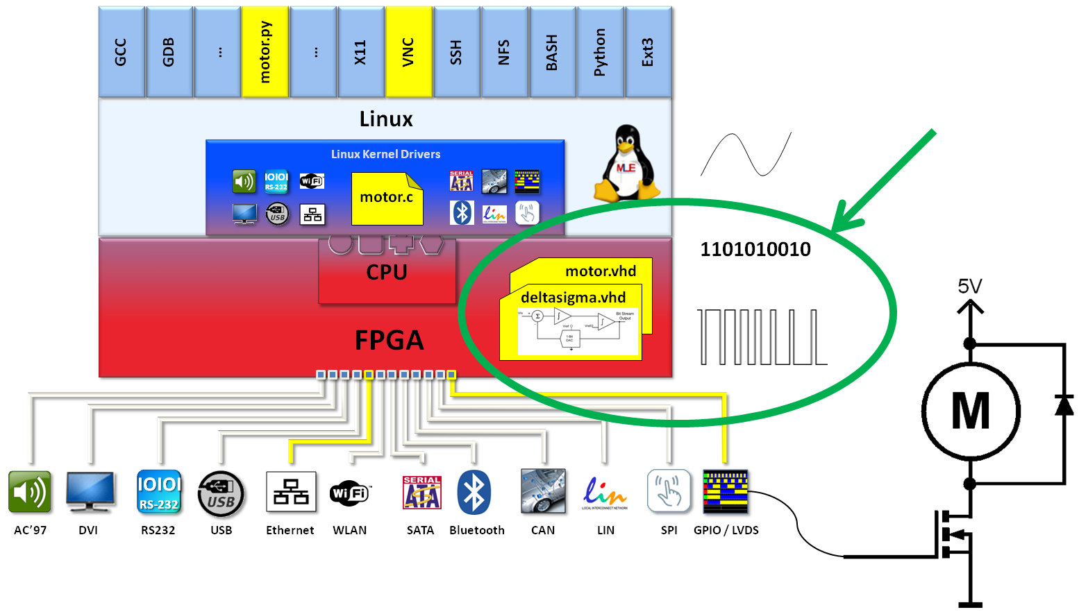
For example, inside the FPGA portion of the MLE 1000 Series Rapid Prototyping System a Sigma-Delta Converter can be implemented to directly interface with analog devices such as a DC motor in Figure 1, for example.
As we will demonstrate, the quality of such analog signal output is comparable to ASIC implementations of digital to analog converters. For this, we have analyzed the noise and the distortion at the FPGA pins and other negative side-effects on the analog audio quality.
While others’ work on Delta-Sigma Converters such as in [Schreier] covers some aspects of that topic, they lack detailed analysis about quality-of-results parameters like signal-to-noise-ratio (SNR) and total-harmonic-distortion (THD) and, for the analog audio playback case, fail to compare those Delta-Sigma-Conversion with other integrated devices.
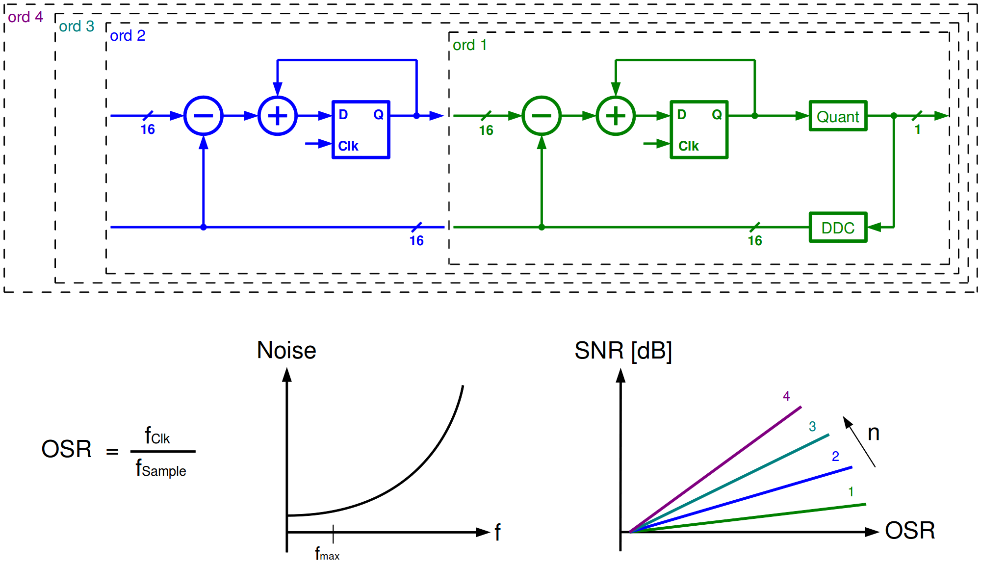
Based on oversampling, a Delta-Sigma-DAC (Figure 2) converts audio samples into a high frequency bit-stream similar to pulse-width modulation. That bit-stream is referenced directly at an FPGA I/O-pin and interpolated using an external analog low-pass filter. The analog output signal consists of average-values-over-time corresponding to the digital sample values. Such analog output signal can directly be used for further amplification and playback, or measurement of audio signal quality in our case. Key advantage of Delta-Sigma-Conversion is noise shaping, which shifts noise from low frequencies to higher frequencies, thus reduces noise in the low-frequency audio domain and therefore results in a very good SNR [Ortmanns]. The SNR theoretically improves with increasing oversampling ratio (OSR) because of lower quantization noise. At the same time SNR improves for higher order Delta-Sigma-DAC. To obtain qualitative and quantitative results, we implemented different Delta-Sigma-DAC configurations for a fully functional audio playback system utilizing the Altera CycloneIII device technology (Figure 3). Obviously, this exemplary setup can be implemented using many other high-quality FPGA devices.
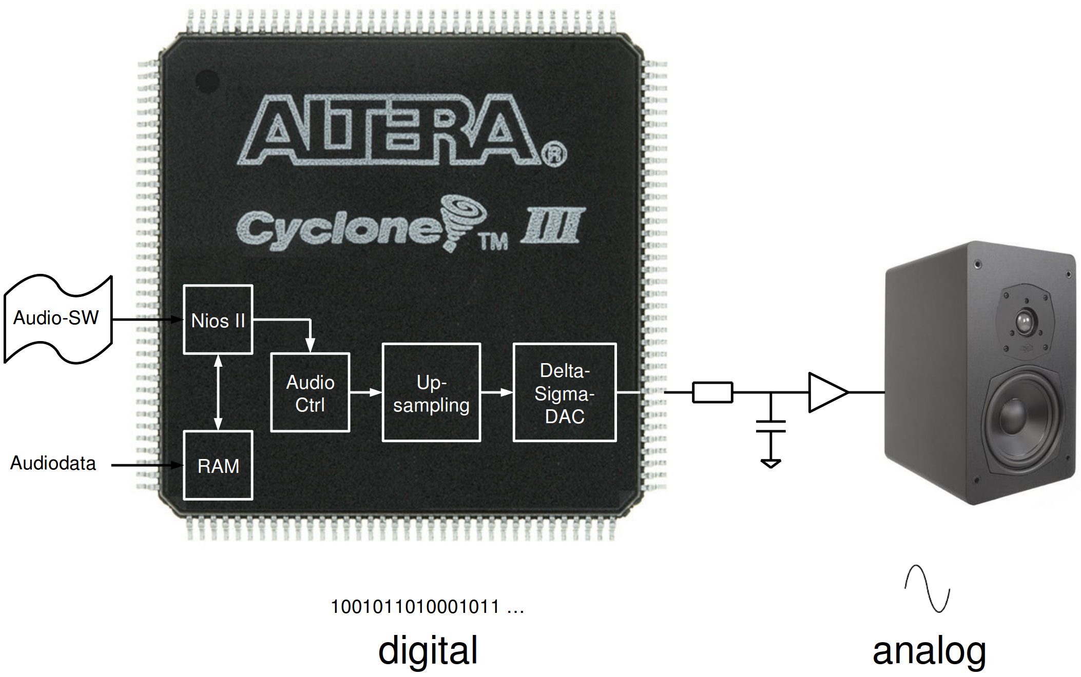
This audio playback system executes audio software in the NiosII Soft-Core processor, sending digital audio data to an audio controller which buffers and synchronizes the audio samples. Digital audio data is then converted via Delta-Sigma-DAC to directly drive an FPGA I/O pin. The FPGA I/O pins are referenced at 2.5V, the external RC low-pass filter is designed for a 20kHz cut-off frequency.
We have experimented with 1st and 2nd order of Delta-Sigma-DAC, as well as different oversampling ratios (using Delta-Sigma-DAC and I/O pin clock speed from 10MHz to 300MHz) and an optional upsampling module. The upsampling comprises an interpolating 1st order Infinite-Impulse-Response low-pass filter and therefore increases the sampling rate prior to Delta-Sigma-DAC. In each case, we measured frequency spectra of discrete sine input signals using an Agilent Network Analyzer and determined SNR and THD.
The required FPGA resources per audio channel are 266 Altera Logic Cells (LC) with upsampling and 196 LC without upsampling.
While all configurations deliver promising audio quality, we came accross the following effects:
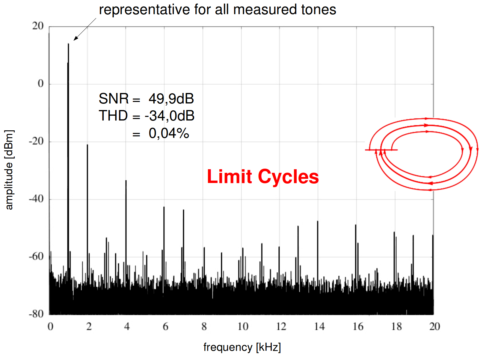
A higher oversampling ratio reduces quantization noise, however, at the cost of THD (harmonic distortion are integer muliples of the input signal frequencies). Due to high oversampling, long repeating patterns occur and the Delta-Sigma-DAC oszillates – a phenomena typically referred to as “limit cycles”. The inherently instable 2nd order Delta-Sigma-DAC does require extra work for stabilization. Upsampling as a pre-processing prior to Delta-Sigma-DAC results in significant improvements. As an explanation, the higher sampling rate means lower oversampling and therefore reduced effects of limit cycles, but the higher number of samples also means higher precision and therefore lower quantization noise. Over all measured sine input signals, both SNR and THD improve by approximately 6dB.
Figure 4 shows a representative output spectrum of a 1kHz sine input signal for the configuration 1st order Delta-Sigma-DAC at 100MHz with upsampling.
To put these results into perspective, we compared our FPGA-based audio playback system with common consumer electronic audio devices, a Realtek ALS268 audio chip according to Intel HD-Audio standard and an iPod Nano 4, using the same measurement setup and the same 1kHz sine input signal.
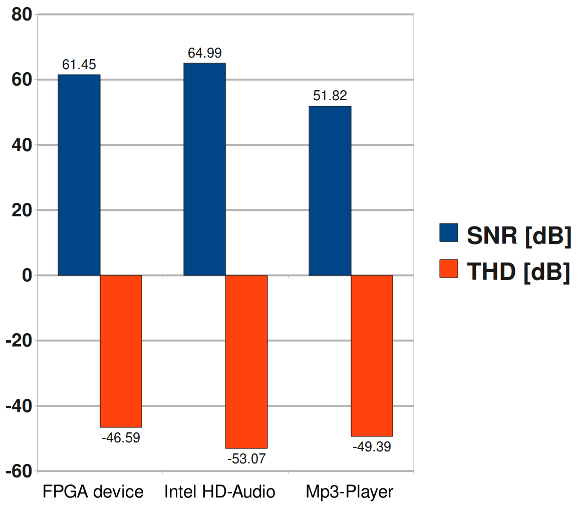
Figure 5 suggests that the SNR of the FPGA approach is comparable to consumer electronic devices, while the THD is slightly worse, likely because of the effects of limit cycles. However, we are confident that additional techniques to counter limit cycles in our FPGA Delta-Sigma-DAC can bring the quality of result of FPGA audio at par with consumer electronics.
Rapid system prototyping systems such as the MLE 1000 Series Rapid Prototyping System are significantly enhanced by the flexibility and performance of today’s FPGA I/O-pins. This enables designers to obtain high quality analog output directly out of an FPGA. FPGA-based Delta-Sigma-DACs can be simple and compact, as the one we have implemented here, and yet provide competitive audio playback results.
For further analysis we plan to look into higher-order Delta-Sigma-DAC, in expectation for even better SNR and lower distortion by limit cycles. Because higher orders of Delta-Sigma-DACs are inherently instable, coefficient-tuning for a stable behavior is mandatory. This is complex, but worthwhile exploring. An additional option is dithering, which means adding a “low dose” noise to the input of each Delta-Sigma-DAC’s quantizers. We expect this to overcome the limit cycle issue in Delta-Sigma-DAC and to result in a better THD.
References
[Schreier] R. Schreier:
An empirical study of high-order single-bit delta-sigma modulators, 1993.
IEEE Transactions on Circuits and Systems II: Analog and Digital Signal Processing,
[Ortmanns] M. Ortmanns:
Continuous Time Sigma-Delta A/D-Conversion, 2006.
Springer-Verlag, 2006
🌐 www.missinglinkelectronics.com
MLE (Missing Link Electronics) is offering technologies and solutions for Domain-Specific Architectures, which focus on heterogeneous computing using FPGAs. MLE is headquartered in Silicon Valley with offices in Neu-Ulm and Berlin, Germany.